| Author |
Message |
Christopher Schimke
Samba Member

Joined: August 03, 2005
Posts: 5391
Location: PNW

|
 Posted: Sat Sep 05, 2009 8:53 pm Post subject: DIY wheel alignment (Updated with missing material) Posted: Sat Sep 05, 2009 8:53 pm Post subject: DIY wheel alignment (Updated with missing material) |
 |
|
| tschroeder0 wrote: |
Hi all,
I just finished up a total front suspension rebuild. It all turned out well. The van goes down the road very good, with the exception of a slight pull to the left(drivers side)
My question is are there any generic measurements/adjustments that can be made prior to an alignment...I'm also thinking if I had a bit more knowledge I may not need to get one.
fyi, I put all the adjustable parts back to the prior measurments with the exception of the rods that go from the lower controll arm to the front bulkhead ( the new bushings prevented this, so I snugged them and made them even) |
In response to tschroeder0's question about what alignment operations can be performed at home, I decided to do a little piece on doing a complete alignment at home. I did not invent any of these procedures, but they have been time tested and depending on how much attention is paid to the details, it can actually be more accurate than an alignment done at a professional shop, and can definitely be more accurate than an alignment done by someone who neither cares nor knows about the specifics of the Vanagon. The added benefit is that once you know the ins and outs of the procedures and have established a good baseline alignment for your self, you will be able to do little tweaks to the adjustments to suit the needs of your van and not have to rely on someone else to do it for you.
I have performed these procedures many times with excellent results. A handful of years ago, I got lazy and didn't want to deal with the alignment that my van needed, so I decided to "treat" myself to a professional alignment. After MUCH frustration and a couple of different alignment shops, I finally found one shop that did a halfway decent job, although it was not anywhere close to perfect. I have resorted to doing it myself from now on.
There are many adaptations and interpretations of these procedures and each one has its own level of accuracy as well its own level of complication. The more attention you pay to the details, the better your results will be, regardless of how complicated (or not) you choose to make your set-up. This is the way that I do it, but there is definitely room for modification and/or improvisation.
Since the Bentley manual does a fine job of showing you what to adjust in order to achieve the alignment specs, this article is only meant to give you an insight into the specifics of the set-up involved in doing an alignment and the tools needed for that set-up as well as how to interpret the specifications spelled out in the manual and is not a full step-by-step alignment how-to.
The first order of business is to be sure that your vehicle is ready for an alignment. Worn or loose components all need to be addressed prior to doing an alignment. I don't think that I need to tell you that doing an alignment on a vehicle with worn or loose components is not only a waste of time, but it will also yield inaccurate results. Tire pressures must all be checked and adjusted to specs if necessary.
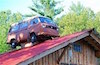
Once the vehicle is ready, you will need to provide a nice level area for your alignment procedures. Doing an alignment on an uneven surface will lead to false readings. Although garage floors seem relatively flat, there is usually a fair degree of slope in at least one direction. To compensate for any uneven ground and to be sure that the vehicle is positioned on as level of a surface as possible, you can use 12x12 floor tiles or 12x12 Masonite to shim the areas of the floor in which the vehicles tires will be sitting. To demonstrate how to perform this leveling procedure, I have chosen to show you how it is done using my driveway as a semi-extreme example.
Position the vehicle where you want to do your alignment and mark the spot where each tire makes contact with the ground. A sharpie, tape, chalk or whatever will work fine, just as long as you have a reference point for where each tire sits on the ground.
Now you will want to roll the vehicle straight backwards away from the marks. The reason for moving the vehicle backwards, rather than forwards, is that when you move the vehicle forward into position again (you will see what I mean by this in just a minute), any tiny movements in the suspension components (flex in the rubber bushings included) will be taken up and the suspension components will be in nearly the same position as they are when you are traveling down the road.
With the vehicle out of the way, place two shims of whatever stock you choose (I use 12x12 floor tiles) in the exact positions where the tires will sit. Use your marks that you made previously to position your shims. The reason for two shims in each position will become clear shortly.
With two shims placed at all four tire positions, it is now time to find the highest point of your chosen location. To do this, I use a water level consisting of colored water, a bucket, some clear tubing and a carpenter's square.
With your bucket containing at least one inch of colored water, make sure that the height of the water is such that it comes to at least the midway point of your carpenter's square. I raised my container up to achieve this.
Tape one end of the clear tubing into the water and secure it (duct tape) so that the end of the tubing remains submerged.
Attach the opposite end of the clear tubing to the top of the long end of the square with duct tape and then attach the tubing to the square at the opposite end of the square (about 6-8 inches below the height of your water line) so that the tubing runs along the numbers on square and so that the numbers can be seen.
With the end of the square sitting on the ground next to your container of water, you can suck the water into the tubing (by mouth - be sure your water and container are clean) until it is higher than the level of the water in your container.
If you have done this correctly and there are no air bubbles in the tubing, the water level in the tubing will drop to match the exact height of the water level in your container.
With the water level created, you can now place the end of the square in the middle of each of your shims to determine which location is the highest. Remember that the highest location will read the lowest number on the square. My highest location (left front) measured right at 15" on the square and my lowest location (right rear) measured 16 1/4".
Using the 1/8" thick tiles, I stacked them in the three lowest locations until I achieved a level of 15" on the square of my water level at all four locations. Since the tiles are 1/8" each, it was very easy to figure out how many were needed for each location.
Remember that I mentioned placing at least two shims in each tire location? This allows the last tile to swivel on the one underneath it as well as lets the suspension settle easier should you need to jack up the vehicle for access to the suspension components while adjusting things. Being able to rotate the wheels during the caster adjustment procedure is where this comes into play the most.
To reduce the friction between the last two sets of tiles, I use a little talcum powder on the next to the last tile. I have heard of people using grease, vegetable oil, salt, wax paper, etc. Whatever it takes to reduce the friction is fine.
You now have a level surface worthy of doing your alignment on. It's now time to position the vehicle onto your leveled surface. If you only have few tiles, like I do on the front, it is probably okay to simply drive the vehicle up onto them. However, if your stack is large, like my rears, it is much safer to move the tile stack, position the vehicle next to your marks, jack up the vehicle and place the tile stack under the tire. With the last two tiles lubed, it is very easy to shoot a tile or two out from under the tire while trying to drive up onto them. A flying tile could really cause some damage or seriously hurt someone. Please be careful.
When positioning the jack under the vehicle, it is best to use the control arm as your jacking point. This keeps the suspension loaded while lifting the wheel/tire off of the ground and minimizes any settling of the suspension. Keeping the suspension loaded is important to achieving an accurate alignment.
Now that you have the vehicle all nice and leveled, we can attack the actual alignment procedures. Before proceeding to any of the actual measurements or adjustments, be sure that you load your van in such a way as to represent its typical road going position. For example, at the very least, the van should be half full of fuel and you will want to add weight to the drivers seat to represent the driver. You can carry this as far as you like really. Just make sure that you present an accurate state of the vehicle on its typical day.
Some terminology
Alignment of the front of the Vanagon is comprised of three main specifications - caster, camber and toe.
Caster angle -
The angle of the axis between the upper and lower ball joint, as viewed from the side, relative to 90º from earth, expressed in minutes, degrees inches or millimeters. If you imagine a line drawn through the upper and lower ball joints, the difference between this line and a line drawn 90º to earth is the caster angle. Caster pointing toward the rear of the vehicle is considered positive while caster pointing toward the front of the vehicle is considered negative.
Negative caster angle makes the steering light but causes the vehicle to wander. Positive caster angle makes the steering heavier but also makes the vehicle track straighter. If the caster angle is different from side to side, the vehicle will pull to the side with the lesser amount of positive caster angle.
Camber angle -
The measurement of the inclination, or tilt, of the front wheels, when viewed from the front, relative to 90º to earth, expressed in minutes, degrees, inches or millimeters. If the wheel(s) are pointing straight up, camber is described as zero. If the wheel(s) tilt inward at the top, camber is described as negative. If the wheel(s) tilt outward at the top, camber is described as positive.
Negative camber promotes tire wear on the inside edge but can also increase positive handling characteristics. Positive camber promotes tire wear on the outer edge of the tire and diminishes the positive handling effects of the suspension.
Toe angle
The difference in the distance between the front of the tire and the rear of the tire, measured in minutes, degrees, inches or millimeters. Incorrect toe angle can lead to excess tire wear and poor handling. When the measurement at the front of the tire is less than that of the rear, it is considered toe in. If the measurement at the front of the tire is more than that of the rear, it is considered toe out.
Those are the points that we will need to address and adjust when doing an alignment, but there is one other bit of information that we need to be consider and/or address when doing a basic alignment.
Thrust Angle -
Thrust angle is the collective direction that the rear wheels are pointed relative to the centerline of the vehicle. When the collective direction of the rear wheels is pointed straight ahead, thrust angle is said to be zero.
However it is possible for the collective thrust angle of the rear wheels to be pointing either left or right of the vehicle's centerline. When this occurs, the vehicle will want to go down the road sideways. Have you ever seen those pickup trucks that "crab" down the road? That is caused by the rear axle (and thus the rear wheels) pointing out away from the vehicle's centerline. Thrust angle will be mentioned again once we get into the set-up phase.
Now that we have the main terminology down, I need to say that I will only be addressing the camber and toe at the beginning of this article. The reason is twofold. One is that caster takes more specialized equipment and is more complicated to set up when compared to setting the camber and toe, whereas camber and toe can easily be performed with normal items usually found in the garage and/or available at the hardware store. However, when doing an alignment, caster is always the first operation to be performed (I will add the caster alignment details at a later date). And second, somebody took off with my caster gauge, so I have had to order another one.
Since camber adjustment always comes before toe adjustment, we will address this aspect first. I will show you how to make a simple camber checking device. However, there are other, more expensive, ways to read the camber angle.
First, measure the distance between the rim lips on your wheels and mark this on a length of metal rod, bar, angle or tube. Anything perfectly straight and easy to handle will do. Then cut this bar approximately 3/8-1/2" longer than your mark. Find a bolt that is long enough to go all the way through the bar and protrude out the other side by at least one inch. Drill a hole straight through the tube, right at your rim distance mark, just small enough to allow you to thread the bolt through the holes. If your bolt spins too freely in the bar, add a lock nut to the outside so that you can keep it secure after you taking your measurement (to be explained further on).
Now get yourself a bubble level that will fit onto the bar that you made without making any contact with the tires, the ground or the vehicle bodywork. That is all that you need for tools to take camber measurements.
Some wheels have center spokes or center caps that protrude past the rim lips. In these cases, you will need to improvise in order to get your bar to clear these obstacles. A simple way of doing this would be to cut short section of the same material that the bar is made from and tape them in place where the bar contacts the rim lips. There are many other options so just choose one that works for you. Just make sure that whatever you add to spacer the bar out, the bar always remains parallel to the rim lips. This means that your spacers will each need to be exactly the same thickness or it will through off your measurements.
If you have a digital angle finder, you can forgo the bolt in the bar and simply read the camber angle off of the angel finder. Since not everyone has a digital angle finder (typical needle and weight style angle finders are not accurate enough for precision alignments, but they are better than nothing), I will show you how to find the camber angle without one. If you choose to use a digital angle finder (and I highly recommend it), make sure that your bar rests on the rim lips and does not get hung out on the tire. You want to have a perfectly parallel line from wheel lip to wheel lip.
The bar shown in the photos below does not exactly fit the wheel as properly as it should. It was built for another set of wheels. Even so, as long as one was careful to be sure that the bar was positioned correctly, it could be used just as it is.
Using the bar with the bubble level held tightly against it (taping the level to the bar helps), rest the bar up against the rim lips making sure that the bar points straight up and down. Adjust the bolt in the bar out until the bubble in the level shows perfectly level.
Note that if your vehicle shows positive camber at the time of measurement, you will have to invert the bar so that the bolt is on the bottom and the resulting calculations for camber angle will be for positive camber, not negative camber.
Now it's just a matter of measuring how far that bolt sticks out past the edge of the bar and doing some calculations to find the camber angle
In the following examples, I will always refer to the vehicle load as "empty" when referring to the specs described in the Bentley manual.
The Bentley manual calls for 0' (minutes) camber plus or minus 30' (minutes). One minute is 1/60th of one degree. Plus or minus 30' means that the front wheel camber can be anywhere between -30' and +30' to be considered within specs. In other words, the specs call for the front wheels to be within -0.5º and +0.5º (30' ÷ 60 = 0.5º).
In order to know what the camber angle is in the example portrayed in the picture above (exaggerated to 4mm), we will have to convert the measurement into degrees. Since I am an absolute math idiot, I have to rely on some of the many online calculators for help. Using the right triangle angle calculator on this page http://www.csgnetwork.com/righttricalc.html and converting my 4mm measurement to inches (4 ÷ 25.4 = 0.157), I can plug in my numbers and it will spit out my camber angle in degrees.
I enter the length that the bolt protrudes past the rod in inches (0.157) into the slot labeled Side A and the overall length of my rod as measured from the two contact points on the rim lip (end of rod to the center of the bolt in this case) (17.5) into the slot labeled Side B and push Calculate. The slot labeled Angle A or B is where I read my camber angle. In this case, the camber angle will read 0.51º.
Thats it for camber! Now you can probably see why it is easier to use a digital angle finder, but the math method is accurate and works well too.
With the vehicle still on a properly leveled surface and the camber angles checked and adjusted, it's time to lay out the string network that will allow you to take accurate measurements off of the wheel locations. These measurements are what you will use to adjust your toe angle.
The parts that I used for this string network are two sticks of conduit (must be at least 7' long), string, four jackstands and four clamps. You will also need a quality ruler to set up the string network, but we will get to that in a minute.
Starting with the two sticks of conduit, I drilled holes in each end exactly 73" apart. The exact distance is not important as long as the strings are positioned wider than the widest part of the vehicle and at least 2" wider than the distance between the outer edge of the tires. What is important is that the holes are drilled at exactly the same distance from each other.
With the conduit drilled, you can then tie a string between each conduit through the drilled holes. Tying through the drilled holes ensures that the strings stay exactly the same distance apart. Make sure that the strings are tied so that their lengths are the same between the two sticks of conduit. To determine how long your strings should be, simply make them long enough so that the conduits can be placed at either end of the vehicle on top of the jack stands. The actual length is not important so long as they clear the bumpers of the car. Equal length IS important. See the photos for reference.
Now you can place the two pieces of conduit onto the jackstands that are positioned at each corner of the vehicle. Place a clamp onto the jackstand in such a way that it keeps the conduit from coming off of the jackstand, yet still allows it to be moved from side to side. Pull the strings as taught as possible without tipping over the jackstands.
Please look at the pictures below for reference while reading the above descriptions.
With the strings in place, you will now need to raise or lower the position of the conduit in order to position the string at the exact centerline of the wheel hubs. Again, use whatever means you have to accomplish this. Refer to the photos above for two different approaches.
It is now time to square the strings with the chassis of the vehicle. People use various methods for this, but in the interest of keeping things as simple as possible, I like to measure off of the centers of the hubs. Even though it shows it in the pictures below, it is not perfectly accurate to measure off of the front grease caps. The caps are so easily damaged and distorted over time that they are not suited for precise measurements. The best practice is to remove the grease caps and measure from the end of the spindle.
It's now just a simple matter of making sure that the strings are the same distance between the left and right front hubs and between the left and right rear hubs. This distance will not be the same front and rear, but making the distances the same left to right will set the strings so that they are parallel with the chassis.
It must be noted that it may take several tries in order to get the strings sitting exactly where they should be. I like to do a quick set-up first just making sure that the strings are kind of close. That way, when I do my final settings, the movements that I do to the string at the front of the vehicle does not have too much affect on the measurement at the rear. It usually takes me about three trips around the vehicle to get it right, but if you are not paying attention or don't do an initial setting to get the strings close, you could make many more trips back and forth.
It should also be noted that the string that I used has a thickness of just about 1mm. I like to use the inside edge of the string for my measurement points. String with a lot of fuzz is not going to be very helpful to you as smooth string gives you a crisp line of sight measurement.
Now we can move on to the toe angle adjustments. This is where the thrust angle can come into play. Toe angle adjustments can be performed without the use of the string jig. All it takes is a simple flat bar across each front wheel and a tape measure. Measure in front of the tire and in back of the tire. The difference is your toe angle. There are two problems with this method.
One is that without the strings, when checking/setting the rear wheel toe angle, there is no way to reference to the centerline of the vehicle. This means that even though the left and right rear wheels have the correct toe angle relationship, they still could be pointing off to the left or off to the right of the vehicles centerline. This would result in the vehicle going down the road like a crab as described in the definition of thrust angle.
The second problem is that when checking/adjusting the toe on the front without the strings for reference, there is no way to tell where the steering wheel will be positioned relative to the wheels pointing straight ahead. While the car could still go down the road straight (assuming that the rear toe is set correctly), the steering wheel could end up way off center.
Setting up the strings eliminates both of these issues.
Luckily for us, the Bentley manual spells out the front wheel total toe angle in minutes, millimeters and inches and the rear toe angle is spelled out at zero minutes so as long as it measures equal, your good. Total toe needs to be divided in half to know the single wheel toe angle.
The rest is all very simple. The Bentley manual describes how to center the steering wheel. Once this is done, its a simple matter of measuring from the front lip on the wheel at string height and the rear lip on the wheel at string height and again, the difference is your single wheel toe angle. Combine the measurement differences for the left and right wheels to know the total to angle.
The pictures below show the right front toe angle at 3mm (26mm at the rear lip of the wheel and 29mm at the front lip of the wheel). Assuming that the left front wheel shows the same 3mm toe angle, this would result in a total toe angle of 6mm. An adjustment of 1mm toe out per side (or 2mm total toe out) would be needed in order to adjust the toe angle into specs. Guess I need a minor adjustment!
The pictures below show the real world measurements of the right rear wheel of my van. You can see that both front and rear lips measure 37mm (actually one of the photos looks like 37.5mm, but the ruler is angled slightly making it look that way. Taking pictures while holding rulers is hard) resulting in zero toe angle for the right rear.
That it
really! Honestly guys, I know that it looks like a lot because of all of words, but once you have the string jig and the camber bar built, the rest is really very simple. Any weekend warrior should be able to perform these operations without any real difficulty (frozen nuts and bolts not included).
Once I have received my new caster gauge (a $40.00 investment), I will show how that is done as well. Its pretty easy, but it does involve more steps and requires another set of simple tools and set up.
*NOTES*
A couple of other bits of information that I should add.
It is REALLY helpful if you crawl under your van prior to performing the alignment to be sure that all of the nuts and bolts that you will be playing with during the alignment are able to be broken free without too much hassle. There is nothing more frustrating than having your mind set on performing an alignment, only to spend the entire day fighting one fastener.
The other thing ts that it is very helpful to make the steering wheel immobile once it is centered while checking/setting the toe angle. At least, if the steering wheel is allowed to move, you run the risk of having the steering wheel off center once you are done. At most, you will end up having to recenter the steering wheel every time you change the toe angle. You can lock the wheel into place using anything from wood crammed between the seat and wheel to tie-downs wrapped through the wheel and around the seat.
_________________
"Sometimes you have to build a box to think outside of." - Bruce (not Springsteen)
*Custom wheel hardware for Audi/VW, Porsche and Mercedes wheels - Urethane Suspension Bushings*
T3Technique.com or contact me at [email protected]
Last edited by Christopher Schimke on Mon Sep 07, 2009 9:26 am; edited 3 times in total |
|
| Back to top |
|
 |
blakeck2
Samba Member

Joined: April 10, 2009
Posts: 939
Location: Los Osos, CA
|
| Posted: Sun Sep 06, 2009 12:46 am Post subject: |
|
|
I wish for a set of wheels like that  |
|
| Back to top |
|
|
syncrodoka
Samba Member

Joined: December 27, 2005
Posts: 12007
Location: Santa Cruz, CA
|
| Posted: Sun Sep 06, 2009 12:55 am Post subject: |
|
|
| '98-'00 MBZ CLK- start cruising craigslist. |
|
| Back to top |
|
|
blakeck2
Samba Member
Joined: April 10, 2009
Posts: 939
Location: Los Osos, CA
|
| Posted: Sun Sep 06, 2009 1:09 am Post subject: |
|
|
| syncrodoka wrote: |
| '98-2000 MBZ CLK- start cruising craigslist. |
what year and model? |
|
| Back to top |
|
|
James 93SLC
Samba Member
Joined: January 21, 2009
Posts: 937
Location: NE Ohio
|
| Posted: Sun Sep 06, 2009 4:46 am Post subject: |
|
|
Very nice writeup Chris 
Major sticky info here!
_________________
-------------------------
91 Vanagon Carat
93 Corrado SLC
-------------------------
Photos: http://picasaweb.google.com/slc.corrado
--------------------------------------------------------
tencentlife "Sometimes a pooka is a problem and sometimes it's just a pooka" |
|
| Back to top |
|
|
fairweather
Samba Member

Joined: August 26, 2007
Posts: 663
Location: Aspen, CO
|
| Posted: Sun Sep 06, 2009 5:41 am Post subject: |
|
|
| Definitely sticky worthy, been hoping someone was going to do this for awhile. The timing couldn't be better, I'll be doing his next week. Thanks Chris. |
|
| Back to top |
|
|
240Gordy
Samba Member

Joined: May 15, 2008
Posts: 2354
Location: Vancouver, BC
|
| Posted: Sun Sep 06, 2009 7:44 am Post subject: |
|
|
| blakeck2 wrote: |
| syncrodoka wrote: |
| '98-2000 MBZ CLK- start cruising craigslist. |
what year and model? |
go to your local craigslist page, type mercedes in the autoparts search, and browse the results. All the wheels from the peeps that gotta have the latest styles or who just wrote off their Benz driving like a goof will be there. $2000
wheel sets for $500.00
if you don't mind driving old school wheels, or if like me you prefer the old styles, it is like a candy store.
Fantastic write-up Loogy. Alignments are something I always figured had to be done by a pro, but you know they don't always do a good job either.
_________________
Tencentlife said,
"So, now that you know what you're doing, go to town."
2010 GOLF TRENDLINE 2.5
1985 GL now with more! a 2.1L
H&R SPORT(RED) Springs FRONT , SLAM SPECIALTIES RE6 AIRBAGS REAR |
|
| Back to top |
|
|
90Doka_Guy
Samba Member

Joined: April 08, 2007
Posts: 548
Location: South Jersey
|
| Posted: Sun Sep 06, 2009 6:52 pm Post subject: |
|
|
Epic thread.  Thanks Loogy. Thanks Loogy.
Ill be eagerly awaiting the caster adjustment.
_________________
-'87 Westy
-'90 Tintop
-'90 DOKA |
|
| Back to top |
|
|
tschroeder0
Samba Member
Joined: April 14, 2008
Posts: 2096
Location: Boulder CO
|
| Posted: Sun Sep 06, 2009 7:08 pm Post subject: |
|
|
| Loogy, That is just a freakin awesome write up. I thank you very much! Todd. |
|
| Back to top |
|
|
insyncro
Banned

Joined: March 07, 2002
Posts: 15086
Location: New York
|
| Posted: Sun Sep 06, 2009 8:34 pm Post subject: |
|
|
I have a Longacre computer scale and alignment system I use to neutralize racecars at the track.
Loggy has shown exactly how to accomplish the same thing without spending thousands on the equipment.
It is very interesting to see the weight distribution of a van broken down by each wheel as well.
You can imagine how much experimenting I have done to neutralize a Syncro Westy with a EG33 Subaru motor in it.
This process has helped me dial in the suspensions and most importantly spring rates and valving for custom applications.
Really good to see it done according to the fundimentals.
Longacre also makes a nifty tool to set toe over and over again easily. The tool can be made easily from items found at building supply warehouses.
http://www.longacreracing.com/catalog/item.asp?id=153&catid=5
Nice jog Loggy.
Thanks for sharring.
dylan |
|
| Back to top |
|
|
wbx
Samba Member

Joined: April 11, 2005
Posts: 1254
Location: Monterey, CA
|
| Posted: Mon Sep 07, 2009 4:04 am Post subject: |
|
|
That really is a fantastic write-up, Loogy.
I do have one question, though (maybe i missed it). How do you set up the string so you know it is straight and provides a good reference for toe?
_________________
'84 Westy (first owner).......but my daily driver has pedals
My "perspective" mantra:
A Volkswagen Vanagon is just a material thing,
As such, it is of the earth,
And if i need to, I can let my Van go. |
|
| Back to top |
|
|
Christopher Schimke
Samba Member
Joined: August 03, 2005
Posts: 5391
Location: PNW
|
| Posted: Mon Sep 07, 2009 7:55 am Post subject: |
|
|
Cool! I hope you guys can find it useful when the time comes. I know not everyone wants to get involved in doing their own alignment, but for those who do..........
| wbx wrote: |
That really is a fantastic write-up, Loogy.
I do have one question, though (maybe i missed it). How do you set up the string so you know it is straight and provides a good reference for toe? |
The first major factor in setting up the strings is to be sure that the holes are drilled at exactly the same distance apart in the conduit. This ensures that the strings will always be parallel when drawn taught.
The second major factor is making sure that the strings are tied at the same length (I think that I may have forgotten to mention the strings being tied at the same length). Minor length differences are not a problem, but again, the more accurate you do the set-up, the more accurate the alignment will be. Carry this as far as you care to take it.
The third minor factor is setting the jack stands is approximately the same position at all four corners of the vehicle. This portion of the operation is not really very critical, but it does help to have the jack stands in a somewhat consistent position rather than just placed all willy nilly.
The fourth and final major factor is the act of measuring from the hubs to the string to ensure that the left and right strings are running parallel to the chassis. Equal measurements between the left and right front hubs and equal measurements between the left and right rear hubs will accomplish this. Due to track width differences, the front and rear measurements will most likely be different, depending where exactly you measure from, but as long as they are the same left to right, your golden.
A couple of other bits of information that I should add. (I will add this to the initial post as well)
It is REALLY helpful if you crawl under your van prior to performing the alignment to be sure that all of the nuts and bolts that you will be playing with during the alignment are able to be broken free without too much hassle. There is nothing more frustrating than having your mind set on performing an alignment, only to spend the entire day fighting one fastener.
The other thing ts that it is very helpful to make the steering wheel immobile once it is centered while checking/setting the toe angle. At least, if the steering wheel is allowed to move, you run the risk of having the steering wheel off center once you are done. At most, you will end up having to recenter the steering wheel every time you change the toe angle. You can lock the wheel into place using anything from wood crammed between the seat and wheel to tie-downs wrapped through the wheel and around the seat.
_________________
"Sometimes you have to build a box to think outside of." - Bruce (not Springsteen)
*Custom wheel hardware for Audi/VW, Porsche and Mercedes wheels - Urethane Suspension Bushings*
T3Technique.com or contact me at [email protected] |
|
| Back to top |
|
|
dobryan
Samba Member

Joined: March 24, 2006
Posts: 16505
Location: Brookeville, MD
|
|
| Back to top |
|
|
SteveVanB
Samba Member

Joined: June 01, 2008
Posts: 1645
Location: This side of Daytona
|
| Posted: Mon Sep 07, 2009 9:08 am Post subject: |
|
|
Maybe this is a dumb question, but on a lowered van aren't the rear wheels toed in a little? Meaning the lower it goes from stock ride height the more the rears toe in? If so, does/should this account for anything?
_________________
91 CARAT |
|
| Back to top |
|
|
Christopher Schimke
Samba Member
Joined: August 03, 2005
Posts: 5391
Location: PNW
|
| Posted: Mon Sep 07, 2009 9:18 am Post subject: |
|
|
| dobryan wrote: |
Loogy,
Can you post a picture of your string setup? One pic of the full setup would help me visualize what I think you are saying.
Thanks for writing this up so well. |
OH MY GOSH!!! There was a whole section of the post missing! I wrote the whole thing up in Word and then transfered it over here. Somehow a bunch of it got lost and I failed to catch it. Thank you for asking these questions (now they make sense) as it allowed me to add in the rest of the post. Sheesh!!!
So...if you have already read the post above, please re read it as it has had a new section added to reflect the set up of the string network.
_________________
"Sometimes you have to build a box to think outside of." - Bruce (not Springsteen)
*Custom wheel hardware for Audi/VW, Porsche and Mercedes wheels - Urethane Suspension Bushings*
T3Technique.com or contact me at [email protected] |
|
| Back to top |
|
|
Christopher Schimke
Samba Member
Joined: August 03, 2005
Posts: 5391
Location: PNW
|
| Posted: Mon Sep 07, 2009 9:30 am Post subject: |
|
|
| bigsteveob wrote: |
| Maybe this is a dumb question, but on a lowered van aren't the rear wheels toed in a little? Meaning the lower it goes from stock ride height the more the rears toe in? If so, does/should this account for anything? |
Not a dumb question at all!
In the notes at the end of the Bentley manual, it states
"Some models, from 1986 on, have a lower chasis height. For these vehicles use the "half-load" measurements as the "empty" settings."
_________________
"Sometimes you have to build a box to think outside of." - Bruce (not Springsteen)
*Custom wheel hardware for Audi/VW, Porsche and Mercedes wheels - Urethane Suspension Bushings*
T3Technique.com or contact me at [email protected] |
|
| Back to top |
|
|
Wildthings
Samba Member

Joined: March 13, 2005
Posts: 50352
|
| Posted: Fri Oct 02, 2009 8:16 pm Post subject: |
|
|
| I have done most of my own alignments for decades and have been very happy. Each and every time I have had a professional alignment done I have had bad results. Loogy's explanation is excellent, but needs to be modified slightly for vehicles with steel wheels. Maybe he says this and I just missed it, but steel wheels often have uneven lips at the outer edges that will give bad readings, so you need to build your gauge to fit right at the point where the bead of the tire fits against the rim. I use a hunk of 2x4 instead of the piece of conduit Loogy uses. I cut the 2x4 to fit inside the lip on the steel rim and then modify the contact area of the 2x4 so that it hits the rim exactly at the same position on both ends, this is critical to getting a good alignment. Take the time to get it right. With a 2x4 I can just cut a notch out of one edge to clear the axle or center cap. Instead of the bolt that Loogy uses I just do some calculations and tape the correct thickness shim to one end my level. |
|
| Back to top |
|
|
Vanagon Nut
Samba Member
Joined: February 08, 2008
Posts: 10379
Location: Sunshine Coast B.C.
|
| Posted: Sun Oct 04, 2009 11:07 am Post subject: |
|
|
Having tried my hand at doing a general check of front wheel alignment, this is a most welcome post. I ended up going to an alignment shop, that did a great job. Still, should I ever tackle doing my own, this looks like the thread to read. (yah I'll be replacing the upper arm bushings at some point  ) )
Thanks Loogy!
_________________
1981 Westy DIY 15º ABA
1988 West DIY 50º ABA
VE7TBN |
|
| Back to top |
|
|
?Waldo?
Samba Member

Joined: February 22, 2006
Posts: 9752
Location: Where?
|
| Posted: Sun Oct 04, 2009 11:15 pm Post subject: |
|
|
EXCELLENT POST!
I'm looking forward to learning how to set caster [nudge, nudge]. 
Andrew |
|
| Back to top |
|
|
Christopher Schimke
Samba Member
Joined: August 03, 2005
Posts: 5391
Location: PNW
|
| Posted: Mon Oct 05, 2009 9:14 am Post subject: |
|
|
Thanks guys! Hoping to get to the caster portion this week.
_________________
"Sometimes you have to build a box to think outside of." - Bruce (not Springsteen)
*Custom wheel hardware for Audi/VW, Porsche and Mercedes wheels - Urethane Suspension Bushings*
T3Technique.com or contact me at [email protected] |
|
| Back to top |
|
|
|


