| Author |
Message |
xoo00oox
Samba Member
Joined: February 11, 2010
Posts: 2672
Location: East Nassau, NY

|
 Posted: Sun Jun 10, 2012 4:36 am Post subject: 50-degree 1.8T conversion details Posted: Sun Jun 10, 2012 4:36 am Post subject: 50-degree 1.8T conversion details |
 |
|
I am one week into a build. The goal is to mount a AEB 1.8t engine from a 1999 Passat into a 91 Vanagon using a diesel Vanagon bell housing and oil pan and not use a raised engine cover.
for those who don't know, the diesel Vanagons used an inline 4cyl engine that was tilted onto its side at a 50 degree angle. The early 1.8t engines (AEB and ATW used from 1997 to 2000) will allow the oil pan to just bolt on.
here is the engine as it is pulled from the Passat...
you can easily pull these out and leave the complete wire harness on the engine, just unplug these three electrical connectors, there will be a fourth if the Passat is an automatic.
here is the stock diesel oil pan, oil pump, bell and a transmission from a 2.1 van.
You need to unbolt the bell and remove the input shaft to shorten it 10mm.
if your teeth are strong enough, just bite it off.
Then bolt on the diesel bell. I should note that you will also need a diesel clutch slave cyl. and starter.
Here is the two oil pumps next to each other, all you need from the diesel pump is the pick up tube.
For the flywheel/ clutch, you could use the complete diesel set-up, it will work but is will slip with too much power (anyone know how much?). The better way is to use a flywheel from a early TDi engine...
a disc from a 2.1 van...
and a pressure plate from a VR6 ....
The pilot bearing from the 1.8t is the correct size for the Vanagon shaft.
Last edited by xoo00oox on Sun Jun 10, 2012 5:55 am; edited 1 time in total |
|
| Back to top |
|
 |
SyncroGhia
Samba Member

Joined: August 21, 2009
Posts: 2458
Location: Highnam, UK
|
| Posted: Sun Jun 10, 2012 5:13 am Post subject: |
|
|
Way to go.
This is another one of those "I'm going to do this one day... " and I've run out of time and space right now.
Good work, keep it going.
One thing that I think will be a problem is the right hand engine mounting bracket as I think that the block is a different shape to the JX. You might look at companies that carry out TDi conversions using later blocks like HA Projekts.
I think the left engine mount bracket will bolt up if it clears the turbo.
MG
_________________
T3 Syncro 16 S6 Westfalia Limey SOLD
T3 Syncro 6x6 SOLD
T3 RS6 Bluestar
T3 Tristar Syncro 16 SOLD
T3 Tristar Syncro RHD SOLD |
|
| Back to top |
|
|
xoo00oox
Samba Member
Joined: February 11, 2010
Posts: 2672
Location: East Nassau, NY
|
| Posted: Sun Jun 10, 2012 5:27 am Post subject: |
|
|
Next, we bolted the engine to the transmission and set it on three stands to have a look at things.
looks like we are going to have some height problems.
I wanted to put the engine/ trans in the van to start mocking things up but the van is out at my buddies paint shop so.....
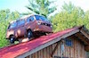
we pushed in a "mock up" van. This is a parts car that we have hacked body parts off of over the past few years.
but first, how to shrink it down?
It took a lot of thinking here, if the intake was made out of steel, I would have cut it up and made the intake runners longer and lower. I don't have a welder or the know how to weld aluminum and I hate to send things out. So after staring at it for a few hours, I had an idea.
Mill the flange at an angle.
|
|
| Back to top |
|
|
xoo00oox
Samba Member
Joined: February 11, 2010
Posts: 2672
Location: East Nassau, NY
|
| Posted: Sun Jun 10, 2012 5:30 am Post subject: |
|
|
| SyncroGhia wrote: |
Way to go.
This is another one of those "I'm going to do this one day... " and I've run out of time and space right now.
Good work, keep it going.
One thing that I think will be a problem is the right hand engine mounting bracket as I think that the block is a different shape to the JX. You might look at companies that carry out TDi conversions using later blocks like HA Projekts.
I think the left engine mount bracket will bolt up if it clears the turbo.
MG |
Thanks Sync...
I'll get to the mounts in a minute. I've got my kids running around me as I try to post this and have to keep stopping.
Andrew- |
|
| Back to top |
|
|
SyncroGhia
Samba Member
Joined: August 21, 2009
Posts: 2458
Location: Highnam, UK
|
| Posted: Sun Jun 10, 2012 5:33 am Post subject: |
|
|
I was going to try the inlet manifold from a BAM engine... like the Audi TT or S3 engine so that it doesn't stick up so high.
MG
_________________
T3 Syncro 16 S6 Westfalia Limey SOLD
T3 Syncro 6x6 SOLD
T3 RS6 Bluestar
T3 Tristar Syncro 16 SOLD
T3 Tristar Syncro RHD SOLD |
|
| Back to top |
|
|
xoo00oox
Samba Member
Joined: February 11, 2010
Posts: 2672
Location: East Nassau, NY
|
| Posted: Sun Jun 10, 2012 5:53 am Post subject: |
|
|
Here is some more intake manafold info
look at the size of the openings...
I looked at a MK4 intake I had, this would bolt on but not give me any clearance.
To clean up the pulley end of the engine, we removed the AC bracket, (I do plan to have AC on this van, but the compressor will need to go on the other side of the engine, different project). The AC has its own belt so it is very easy to remove. and pressed the fan off the hub. Just use three long bolts to press it off.
Next we rolled the assembly under the mock van (these things are a PAIN when they are flopped over at 50*! Nothing like a WBX, it just want to tip over).
Here the trans front mount is bolted in and engine is in position side to side. It looks like we might be good.
Here I have a straight edge showing the "clearance of the top of the engine. I am resting the straight edge on the sheet metal ribs on either side of the engine cover. I know I'll have to modify the engine cover at least by taking the foam off it in the very center, maybe by cutting out a couple of ribbs and putting a piece of 1/8" steel plate over it. But nothing will raise the mattress. Tight is good.
|
|
| Back to top |
|
|
xoo00oox
Samba Member
Joined: February 11, 2010
Posts: 2672
Location: East Nassau, NY
|
| Posted: Sun Jun 10, 2012 6:20 am Post subject: |
|
|
Next, we needed a way to mount the engine to the body.
Here are the stock diesel van mounts..
The left one would have bolted to the motor but the turbo is in the way and I kind of wanted to keep the turbo. The right one did not have any holes that would match up. So, we need to fabricate some. I wanted to use the Passat rubber mounts and use some factory holes in the Vanagon. Here is what we came up with...
This is the left mount just tac welded The big loop is to clear the turbo.
Left mount after finish weld and grind...
Right mount...
These use the same bolt hole in the block as the Passat mounts and use the bolt holes in the Vanagon as the mustache bar in the rear and the diesel motor mount bars in the front of the van, so far no holes have drilled in the van.
Last edited by xoo00oox on Sun Jun 10, 2012 6:56 am; edited 1 time in total |
|
| Back to top |
|
|
xoo00oox
Samba Member
Joined: February 11, 2010
Posts: 2672
Location: East Nassau, NY
|
| Posted: Sun Jun 10, 2012 6:51 am Post subject: |
|
|
Here is the left mount in place...
and the right....
Next, we needed to "clock" the turbo to put the oil drain pointed down and swing the compressor outlet so it was not pointed down to the ground.
here is the stock position...
Here it is after being clocked or indexed...
and bolted back up...
This requires the two oil lines and two coolant lines to be altered. The oil feed line was able to be carefully bent into its new position, the two coolant lines also just required light modifications, the oil drain is a little more work.
The oil pan I am using must have come from a turbo diesel as there is already a drain hole in it for a turbo, however it is too small a diameter for my turbo, I found a drain plug that fits it to plug that hole. Then we drilled and tapped new holes that would match my turbo drain hose.
|
|
| Back to top |
|
|
?Waldo?
Samba Member

Joined: February 22, 2006
Posts: 9752
Location: Where?
|
| Posted: Sun Jun 10, 2012 7:40 am Post subject: |
|
|
In measuring the difference between diesel and gas input shafts, I come up with 11mm difference although the extra mm is likely not of issue unless, of course, the input shaft bottoms out in the hole of the crank. You should also put a decent chamfer on the end similar to the original in order prevent pilot bearing damage during engine/trans removal/installation in the future.
You can machine a channel in the flywheel in order to access the two oil pan bolts and then have it balanced. If you don't do that, you will need to drop the trans and pull the clutch/flywheel to remove the oil pan.
Be sure to use an oil pump pickup tube from a 36mm geared oil pump. The '82-83 diesel vanagons all had 30mm geared pumps and the integral oil pressure control valve is ill-suited to the 36mm pumps. Later euro spec TD vanagons had the right pump/pickup tube and the earlier van pump part number has been superseded to the 36mm pump and so replacement pumps have the correct pickup tube. |
|
| Back to top |
|
|
xoo00oox
Samba Member
Joined: February 11, 2010
Posts: 2672
Location: East Nassau, NY
|
| Posted: Sun Jun 10, 2012 8:49 am Post subject: |
|
|
Excellent points Andrew, I"ll double check the gears on the diesel pump I took the pick-up off and make sure I still have correct end play on the crank so I know if the input shaft is hitting or not.
I was thinking I could access the pan bolts with a ball-end t-handle allen wrench, I'll take a closer look when I am back at the shop on Tuesday.
Thanks for your input.
Andrew- |
|
| Back to top |
|
|
beelzibus
Samba Member
Joined: March 01, 2005
Posts: 300
|
| Posted: Sun Jun 10, 2012 9:52 am Post subject: |
|
|
Nice thread, I've always figured that using the diesel bits and tilting the block over made more sense than using an upright adapter plate. I realise there are clearance issues with the inlet manifold, but to my mind, getting a couple of manifolds chopped up and tigged together by someone handy is a one hit job, will never go wrong and is a neater solution than either an adapter plate or a raised cover. If you've managed to gain sufficient clearance just by machining the manifold mounting flange at an angle, then that is really neat. Great idea.
If I hadn't already gone the EJ25 route with my Syncro Westy I think the 1.8T is the way I'd go, but horses for courses they're both great engines. |
|
| Back to top |
|
|
JustBuggy
Samba Member

Joined: August 01, 2010
Posts: 849
Location: SF Bay Area, Ca.
|
| Posted: Sun Jun 10, 2012 10:40 am Post subject: |
|
|
| beelzibus wrote: |
........
If I hadn't already gone the EJ25 route with my Syncro Westy I think the 1.8T is the way I'd go, but horses for courses they're both great engines. |
What would give you more power, at least in stock trim?
The thing I like about this is you can use recycled parts and don't need custom adapters! |
|
| Back to top |
|
|
xoo00oox
Samba Member
Joined: February 11, 2010
Posts: 2672
Location: East Nassau, NY
|
| Posted: Sun Jun 10, 2012 10:48 am Post subject: |
|
|
| stock, the 2.5 has more. The 1.8t can be bumped up easily with just a chip. |
|
| Back to top |
|
|
Vanagon Nut
Samba Member
Joined: February 08, 2008
Posts: 10371
Location: Sunshine Coast B.C.
|
| Posted: Sun Jun 10, 2012 12:38 pm Post subject: |
|
|
| xoo00oox wrote: |
It took a lot of thinking here, if the intake was made out of steel, I would have cut it up and made the intake runners longer and lower. I don't have a welder or the know how to weld aluminum and I hate to send things out. So after staring at it for a few hours, I had an idea.
Mill the flange at an angle.
|
Thanks for posting your build.
Is there any chance the thinner metal will crack from heat cycling, vibrations?
I'm curious if it's feasible to make an angled aluminum "wedge" between intake and head instead of removing material.
Maybe adding a gasket is asking for a leak? Maybe the added material would move manifold over in to the way of other stuff?
Neil.
_________________
1981 Westy DIY 15º ABA
1988 West DIY 50º ABA
VE7TBN |
|
| Back to top |
|
|
rubbachicken
Samba Member

Joined: October 05, 2004
Posts: 3058
Location: socal
|
| Posted: Sun Jun 10, 2012 9:07 pm Post subject: |
|
|
| Vanagon Nut wrote: |
| xoo00oox wrote: |
It took a lot of thinking here, if the intake was made out of steel, I would have cut it up and made the intake runners longer and lower. I don't have a welder or the know how to weld aluminum and I hate to send things out. So after staring at it for a few hours, I had an idea.
Mill the flange at an angle.
|
Thanks for posting your build.
Is there any chance the thinner metal will crack from heat cycling, vibrations?
I'm curious if it's feasible to make an angled aluminum "wedge" between intake and head instead of removing material.
Maybe adding a gasket is asking for a leak? Maybe the added material would move manifold over in to the way of other stuff?
Neil. |
what's left after the manifold has been machined looks thick enough still, especially if there's some where it could braced back to the block, then there would be no chance of a problem
_________________
lucy our westy
lucy's BIG adventure
meet 'burni'
markswagen {mobile mechanic} san diego area all early VW's cared for.
619 201 0310 or 617 935 4182 |
|
| Back to top |
|
|
Vanagon Nut
Samba Member
Joined: February 08, 2008
Posts: 10371
Location: Sunshine Coast B.C.
|
| Posted: Mon Jun 11, 2012 11:52 am Post subject: |
|
|
| rubbachicken wrote: |
| Vanagon Nut wrote: |
| xoo00oox wrote: |
..... So after staring at it for a few hours, I had an idea.
Mill the flange at an angle.
|
... any chance the thinner metal will crack from heat cycling, vibrations?
I'm curious if it's feasible to make an angled aluminum "wedge" between intake and head instead of removing material.
|
what's left after the manifold has been machined looks thick enough still, especially if there's some where it could braced back to the block, then there would be no chance of a problem |
Yah I imagine so. And to boot, if thinnest part of wedge were as thick as OEM flange, the angle and length at thicker part of wedge would likely put intake into a non workable spot.
Having done a swap involving fabricating, my POV tends to involve "what if" scenarios on parts changed or built. To be clear, was just looking out for OP not being critical of his work.
Anyhow. Back to the programme already in progress..... 
Neil.
_________________
1981 Westy DIY 15º ABA
1988 West DIY 50º ABA
VE7TBN |
|
| Back to top |
|
|
SyncroGhia
Samba Member
Joined: August 21, 2009
Posts: 2458
Location: Highnam, UK
|
| Posted: Mon Jun 11, 2012 11:54 am Post subject: |
|
|
I'd imagine that with a proper support at the other end of the manifold, it should be fine.
I don't think you've got enough of an angle that to cause too many bolt head to manifold seating issues.
If you can spot face where the bolt heads sit, that would be good.
MG
_________________
T3 Syncro 16 S6 Westfalia Limey SOLD
T3 Syncro 6x6 SOLD
T3 RS6 Bluestar
T3 Tristar Syncro 16 SOLD
T3 Tristar Syncro RHD SOLD |
|
| Back to top |
|
|
xoo00oox
Samba Member
Joined: February 11, 2010
Posts: 2672
Location: East Nassau, NY
|
| Posted: Wed Jun 13, 2012 2:44 am Post subject: |
|
|
I got started on the exhaust yesterday....
I cut the flange off the original converter where it bolts to the turbo and welded to that. 2.5" dia pipe. |
|
| Back to top |
|
|
Christopher Schimke
Samba Member

Joined: August 03, 2005
Posts: 5390
Location: PNW
|
| Posted: Wed Jun 13, 2012 6:30 am Post subject: |
|
|
Man, this is really cool!
_________________
"Sometimes you have to build a box to think outside of." - Bruce (not Springsteen)
*Custom wheel hardware for Audi/VW, Porsche and Mercedes wheels - Urethane Suspension Bushings*
T3Technique.com or contact me at [email protected] |
|
| Back to top |
|
|
insyncro
Banned

Joined: March 07, 2002
Posts: 15086
Location: New York
|
| Posted: Wed Jun 13, 2012 6:50 am Post subject: |
|
|
| Christopher Schimke wrote: |
| Man, this is really cool! |
X2
I need to stop by and check it out in person.
Keep up the good work.
dylan |
|
| Back to top |
|
|
|


