| Author |
Message |
TDCTDI
Samba Advocatus Diaboli

Joined: August 31, 2013
Posts: 12856
Location: North Carolina

|
 Posted: Mon Jun 22, 2015 7:07 pm Post subject: Posted: Mon Jun 22, 2015 7:07 pm Post subject: |
 |
|
Awww, thanks Richard.  |
|
| Back to top |
|
 |
dustymojave
Samba Member
Joined: January 07, 2007
Posts: 5802
Location: Lake LA, Mojave Desert, SoCal
|
| Posted: Mon Jun 22, 2015 10:56 pm Post subject: |
|
|
| smileyman3000 wrote: |
I only have 2mm of bumpsteer at the edges of the front tyres in the usable travel range.
I can tell you my stock bug steering had more than that.
All it comes down to is getting that rack in the correct spot.
If I end up breaking it I will just change to something stronger, it's no big deal.
The main reason for the end load though is because space is at a bit of a premium under the front tank. Even with a bodylift I have to find space for the hydraulic clutch M/C, oil cooler, aircon condenser and aircon dryer. Plus fuel lines, oil lines and aircon lines too!
Smiley  |
Just put all the AC stuff behind the grille and in front of the radiator. 
So how much are you considering "the usable travel range"?
_________________
Richard
Offroading VW based cars since 1965
Tech Inspection 1963 - 2012 SCCA/SCORE/HDRA/MORE/MDR +
Retired from building Bajas, Fiberglass Buggies and Rails in the Mojave Desert. Also Sprints & Midgets, Dry Lakes, Road Race cars. All types New and Vintage
SoCalBajas Member
Kicked Cancer's A$$...1st and 2nd round...Fight ain't over yet. |
|
| Back to top |
|
|
Hnoroian
Samba Member

Joined: October 27, 2013
Posts: 535
Location: Bakersfield
|
| Posted: Mon Jun 22, 2015 11:24 pm Post subject: |
|
|
Looks killer! I don't know if I missed it but do You plan on a roll cage? Or are they not AU DOT legal?
_________________
Stupid people do stupid things. |
|
| Back to top |
|
|
smileyman3000
Samba Member

Joined: November 07, 2010
Posts: 238
Location: Yeppoon, Australia
|
| Posted: Tue Jun 23, 2015 1:33 am Post subject: |
|
|
| dustymojave wrote: |
Just put all the AC stuff behind the grille and in front of the radiator.
|
Don't have a grill or a radiator! I'm not putting a waterboiler in my bug! 
| dustymojave wrote: |
So how much are you considering "the usable travel range"? |
Well it has a bit over 300mm with no stops. And right at the bottom of the travel at full droop when the arms and spindles all run into each other the wheels toe out about 6mm.
I'm planning to limit the travel to about 250mm. But ultimately that will depend on how the stops fit with the arms and how much up travel the wheels can have before they hit the guards.
The 'usable travel' I'm talking about is this 250mm or so. And within this travel range there is only 2mm of toe change at the wheel.
| Hnoroian wrote: |
| Looks killer! I don't know if I missed it but do You plan on a roll cage? Or are they not AU DOT legal? |
No plans to run a cage at this stage. A few years ago it wasn't so hard to do. But Queensland changed the laws and now anything over a 4 point cage is illegal for a registered car. (Yeah I know, how dare you make you car safer!!)
So I figured a single hoop roll cage is a bit of a waste of time and will just make it more difficult to get stuff out of the backseat or fridge. And reduce the interior space and headroom.
Smiley |
|
| Back to top |
|
|
smileyman3000
Samba Member
Joined: November 07, 2010
Posts: 238
Location: Yeppoon, Australia
|
| Posted: Thu Jun 25, 2015 6:10 am Post subject: |
|
|
While I had the body sitting on the pan I decided to cut the rear shelf out for my rear tank. I'm going to recess it down this time. So it will be much the same as the front tank. With a large hole that the tank fills and seals.
For those of you that don't know I was running a Bay Kombi tank in the rear as my main tank and using the stock front tank as a secondary. It sat in this frame here and there was a little hole cut in the rear floor for the outlet on the tank.
First thing was drill out the spot welds and remore the front lip. And just when you think you have gotten all the rust
And then cut a big hole for the tank!
Tried the tank in the whole but it wasn't quite sitting down all the way on one side.
One big concern that I had was clearance to the airbag frame and to the starter motor. But I'm happy to report that there is heaps of room to both of them.
Turns out the tank was hitting on one of the shock lumpy bits on the LHS. So I enlarged the hole in it a little and the tank fits down perfectly now!
Then I went back inside and took the edges of the hole all the way to the wheel wells so I can start on a frame for the tank.
Now that that was all sorted the body came back off and out of the way. I can do the tank mount with the body off, now that I know it will clear everything.
I welded some extra strengthening plates onto my bag mount.
First was this little tab. Which picks up one of the holes cast into the shock tower. Perfect size for an M12 bolt
Next up I added this angle which ties in to the upper shock mount. These were all welded out once I got them fitting nicely. But it seems I didn't get a picture. Perhaps tomorrow.
Last thing for today was strip the box, rear arms and everything off the pan. Gave it a good sweep down and flipped it. Ready for tomorrow which involves all these pretty pieces
Thanks for reading.
Smiley |
|
| Back to top |
|
|
HERC
Samba Member
Joined: July 30, 2007
Posts: 1003
Location: Menifee
|
| Posted: Thu Jun 25, 2015 6:43 am Post subject: |
|
|
That looks great. You better patent that bag system, that'll pay for everything.
I suppose that fuel tank gives me the creeps at its proximity to those power cables and field coils.
_________________
Herc |
|
| Back to top |
|
|
smileyman3000
Samba Member
Joined: November 07, 2010
Posts: 238
Location: Yeppoon, Australia
|
| Posted: Mon Jun 29, 2015 5:39 am Post subject: |
|
|
I decided that I would need to sort my shift linkage out before running any of the stuff in the tunnel. It is one thing that will need to be in there so I don't run hoses through where it is going to be. I will also need to fit the pedals too and make sure everything clears them in the tunnel as well.
So flip the pan back over and refit the box. Then cut a hole in the lift for the shift linkage.
Ran into a bit of clearance issue on the top of the framehorn. Had to do a small amount of 'reshaping'.
After that it all hooked up as planned and I fitted a gearstick and 'seat' so I could try it out. For those that haven't read the older posts on here, the shift linkage is part VW and part Holden Commodore steering linkage. The shift rod is slightly shorted than stock and has the spline off the top of the Holden steering rack welded into it. The Holden steering shaft clamps tightly onto the Weddle linkage and then slides over the splined end on the shift rod. Happy to report that I can get all the gears pretty easily. Reverse takes a tiny bit of extra wiggling but I haven't adjusted anything yet. Also there is no shift rod bushing fitted in the front mount behind the gearstick. Plus nothing is lubricated either.
Still a little bit of clearancing to do around the hole. I also have to enlarge it enough for the uni joints on the shaft to fit through.
Thanks for looking.
Smiley |
|
| Back to top |
|
|
smileyman3000
Samba Member
Joined: November 07, 2010
Posts: 238
Location: Yeppoon, Australia
|
| Posted: Wed Aug 05, 2015 3:23 am Post subject: |
|
|
Made up a spacer for the Kombi shifter out of 8mm plate. Fits nicely now and shifts quite good for having no front shifter bushing in. I was thinking of trimming the bus shifter down, but now it has grown on me. I put both the seats in with a passenger and tested how the gearstick cleared everything with both seats forward and backward in different spots and two people sitting on them. Happy to say it clears everything very nicely. And I like the height. So I might stick with it yet.
I purchased a heap of stauff clamps for everything that is going in the tunnel. You can remove the think upper plate and bolt and replace them with an allen socket bolt which is countersunk into the plastic. Saves space inside the tunnel (which is at a premium these days!!) and saves some weight too. Because I am not using the clamps for high pressure hydraulic lines the single bolt will be quite adequate.
T3 pedal assembly was robbed of its clutch master cylinder to use in the car. I figured this would be the simplest and easiest way to go as it matches the slave cylinder on the box and the bits are all from the same car. Bored a hole in the lift kit where the brake M/C was originally mounted. Then made up a mount out of some angle and tacked it in place so I could work the pedal side of things out.
Then the brake m/c was moved over to give sufficient room. More holes drilled.
I added a new pivot to the brake pedal that I stole off another set. You can see the stock one is still on the left side of the pedal. This one will be cut off and moved over to the clutch pedal for the clutch M/C. Fitted the pin and pedal travel is exactly as it should be.
Dropped the body on to check a few things. Fitted the seat in the car for the first time. Happy to say that the height is absolutely perfect for me. It is exactly where I want it. Pedals feel good underfoot too.
The seat has plenty of room to the door too which is good.
Need to work out where I am going to fit the fill reservoir. Probably somewhere under the bonnet that will go down to both the M/Cs.
Last thing I started thinking about/playing around with is fitting a hanging accelerator pedal. Here is one I had lying about from a Commodore. Jury is still out at the moment. I think it won't take much to fit up and connect. I just like the idea of less stuff on the floor and not having the pedal hinge seize up/fill up with sand and crap etc.
Thanks for looking
Smiley |
|
| Back to top |
|
|
dustymojave
Samba Member
Joined: January 07, 2007
Posts: 5802
Location: Lake LA, Mojave Desert, SoCal
|
| Posted: Wed Aug 05, 2015 11:10 pm Post subject: |
|
|
Good work on this pedal stuff. It's going to wind up looking like the factory built it that way.
_________________
Richard
Offroading VW based cars since 1965
Tech Inspection 1963 - 2012 SCCA/SCORE/HDRA/MORE/MDR +
Retired from building Bajas, Fiberglass Buggies and Rails in the Mojave Desert. Also Sprints & Midgets, Dry Lakes, Road Race cars. All types New and Vintage
SoCalBajas Member
Kicked Cancer's A$$...1st and 2nd round...Fight ain't over yet. |
|
| Back to top |
|
|
Indy45
Samba Member
Joined: July 31, 2015
Posts: 37
Location: Missouri Ozarks
|
| Posted: Sat Aug 08, 2015 7:32 pm Post subject: |
|
|
| read this thread tonight from start to here, LOVE it, cant wait to see more!!! |
|
| Back to top |
|
|
smileyman3000
Samba Member
Joined: November 07, 2010
Posts: 238
Location: Yeppoon, Australia
|
| Posted: Fri Sep 04, 2015 4:26 pm Post subject: |
|
|
| dustymojave wrote: |
| Good work on this pedal stuff. It's going to wind up looking like the factory built it that way. |
| Indy45 wrote: |
| read this thread tonight from start to here, LOVE it, cant wait to see more!!! |
Thanks for the kind words guys 
Got a little bit done in the last few days.
Got to work mounting up the dual handle cutting brakes. I cut the front of the mount frame off and left it bolded to the arm pivot. And then put everything in place on the pan so I could work out how it's going to fit.
Made up some mounting plates for the cylinders which will be welded o the tunnel.
Next up I dug out the handbrake that I will be using to check clearances. Going to be tight. I had to move the cutting handles forward a touch on the tunnel and notch the underside of the handbrake out a bit. But it all fits and the handbrake works like normal. You can see I will have to trim the handles back a little as the left side one doesn't clear the gearstick anymore with them moved forward on the tunnel.
And here is everything in place and welded up. I made some extended pushrods by welding a pair of nuts onto the head of some bolts I got to suit the length. The fit is all very good and All the handles work as they should. I'm thinking I might cut the handbrake length down a bit to give more room to grab the ends of the cutting handles.
Next up flip the pan over again so we can finally get onto mounting the stuff in the tunnel.
I started from the back and worked forward. Welding in the stauff clamps for the aircon lines first up.
Once we got up under the pedals I cleaned everything up and added a few strengthening plates across the seam where I welded the framehead on. Should be super strong now! Then the lines could be looped around the pedals. I cut the hook off the clutch pedal to give some more room, and stop it rubbing on the hoses.
I also added a doubler plate on the framehead where the bulkhead fittings are coming through.
Then I welded the plates to the other side of the tunnel for the oil hoses. And the smaller ones below this for the fuel hardline.
I ordered some sexy AN fittings for the fuel hardlines. I drilled the lift kit at the back for the bulkheads. Sorry about the shoddy picture, the pan was still upside down. You can still get an idea of where they exit out the back.
Last thing I got down was to drill holes along the tunnel and weld nuts onto the inside. These are for the clamps that will hold my brake and clutch hardlines in place. The brake is on the right of the tunnel and the clutch down the left. You can see the spots along the tunnel where I buffed the paint off. I need to get some shorter bolts though, cause the ones I have stick into the tunnel too far where some of the hoses are going to be.
I also discover that my floorpan can stand up all by itself, even with the gearbox bolted into it
Things are getting a little busy up the back here. I still have to add a new accelerator cable tube too. But I am confident that everything will fit! I still need to work out some way of sealing the shift linkage to the floorpan where it comes through the lift. Does anyone have any good ideas for this??
Lastly, I bought a new second battery for the car. This one will be dedicated to running the fridge and camp lights. Whereas the other will be for most everything else.
Still a few things I need to do in the tunnel before I paint it up and weld it shut again. Mostly fitting the front bulkheads fittings and making up the oil hoses and fuel lines. And adding the new accelerator tube. In addition to this I have picked up my rear guards which have been repaired, as well as the engine scoop. The front guards that I had widened turned out to be rubbish So I have taken another set to a different guy that has been doing my glasswork and he is widening them for me again.
Still heaps to do but things are falling into place slowly.
Thanks for looking.
Smiley |
|
| Back to top |
|
|
smileyman3000
Samba Member
Joined: November 07, 2010
Posts: 238
Location: Yeppoon, Australia
|
| Posted: Wed Oct 14, 2015 7:25 am Post subject: |
|
|
I haven't worked on the car for a few weeks. Spent a week at Fraser and then down south for Warwick VW drags etc.
But prior to that I got a bunch of stuff done.
Firstly I got a care package from USA. Porsche CVs!! Thanks Rich!
Then I got to work mounting up the stainless hardlines I had made. And fitting up the bulkheads where they come out the front and back of the pan. Unfortunately I measured a tiny bit short and the clutch line didn't quite reach. I had to have to remade about 50mm longer. I had the same issues with the brake line to the cutting brake. But was able to fix this with a banjo that has a longer end.
Next up I fitted the new accelerator cable tube into the tunnel. And welded in the last hose mount plates.
Then I started making and fitting up the new fuel hardlines for in the tunnel.
Once that was done I did another trial fit of everything to see that it all clears and fits around the shift rod etc.
Smiley |
|
| Back to top |
|
|
smileyman3000
Samba Member
Joined: November 07, 2010
Posts: 238
Location: Yeppoon, Australia
|
| Posted: Wed Oct 14, 2015 7:42 am Post subject: |
|
|
I soon discovered a new issue that I had created.
It was impossible to get the shift rod out through all the hoses to change the bushing.
So I went and got a new gearstick tunnel piece off a spare scrap pan I have.
And cut the original shift hole out of the tunnel.
I welded flat bar around the perimeter of this new hole and made the tunnel piece into a cover/removable shifter bushing. Very much like what a Type 3 has.
Then I had another issue. I could now remove the shift rod out the top of the tunnel. But it would hit the firewall inside the car before it came all the way out of the tunnel. Easily fixed, just cut it in half!!
I welded a nut into one side and a bolt into the other. A locknut holds it all in place. This allows me to break it in half, but also gives me a little length adjustability and I am able to rotate the splined end to wherever I want it too.
So the new shift bush replacement instructions are to disconnect the linkage. And remove the gearstick and then the shifter plate.
Pull the shift rod out and crack the locknut.
And then unscrew the front half and change the bushing. Simple!
Got my new clutch line back. Right length this time!!
Made the line up to the master cylinder.
[
This line was fixed with the longer banjo.
And started making up some of the rear lines.
Smiley
Last edited by smileyman3000 on Wed Oct 14, 2015 8:16 am; edited 1 time in total |
|
| Back to top |
|
|
smileyman3000
Samba Member
Joined: November 07, 2010
Posts: 238
Location: Yeppoon, Australia
|
| Posted: Wed Oct 14, 2015 8:13 am Post subject: |
|
|
I was trying to get all of the welding on the pan finished off that needed doing. Next up was the battery, solenoid and compressor mounts.
I picked up some good rubber matting to put under the batteries. And I cut some bit of angle to weld to the pan to stop them moving around. I put 2 on each battery on diagonally opposite corners.
Next I fitted a cut down piece of angle to the tunnel for the dual battery solenoid.
Then I welded on a couple of tabs that I drilled and tapped for my battery hold downs. Cut some more angle to use as the strap. Just need to get some bolts and it's ready to go. I will probably also add some rubber between the strap and battery too.
Then I made up a little frame for my ARB compressor that will be going next to the battery. Took me a little while to get the height and fit right but it all looks sweet now and fits perfectly next to the battery.
Next stop was the front beam. I added plates front and back to both beam tubes. This is where the beam support will bolt on. And where the front barwork will bolt to in the future.
Unfortunately I cooked my inner beam bushings while doing this so they had to come out. Took a bit but I got there with the slide hammer eventually.
I fitted the outer bearings and assembled the suspension so I could cycle it for the stops.
I cut a hole in the plate and welded a cut up rear swinger snubber mount on to the plate. So I will be running rear snubbers on the front too. Added a gusset plate. to the back too. I don't seem to have taken many pictures of this. I'm not sure if I like this setup yet. I might cut it all off and change it yet...
I cut and ground the hole in the front of the framehead as big as I can. Not I can fit my whole arm in there. Not sure if I can with the beam on though.
Fitted up my rear support frame and cut the tubes down to the new length needed and welded them on.
Put a plate in to block the last gap between the torsion housing and lift.
Filled in this stupid idea of a hole under the rear torsion housing. All bugs have this, I'm not sure why but it does a great job of letting crap into your tunnel. I welded a little plate over it.
Rewelded the hooks onto the outer edge of the pan. And plated them up too. I will probably add an extra plate between the torsion housing and the pan too.
Smiley |
|
| Back to top |
|
|
smileyman3000
Samba Member
Joined: November 07, 2010
Posts: 238
Location: Yeppoon, Australia
|
| Posted: Wed Oct 14, 2015 8:33 am Post subject: |
|
|
Time to seal the tunnel up! Started by making up some plates to cover it up. I decided to do it in three pieces. One weird shaded piece at the back, the main longer piece along the tunnel and the large one up the front that is also the base fro the framehead. I staggered the front join in a different spot to where the framehead has been welded to the tunnel for maximum strength. I'm using the same 2.1mm checkerplate that my floorhalves are made from.
Then the inside of the tunnel was buffed, ground, wirewheeled etc until I had it as clean as possible. Then I painted it all with weld-through primer.
Next up I fitted all the hoses and lines. I added a drop of medium strength Loctite to the clamp bolts. Hopefully it all stays there for a very long time.
I added some flatbar across the tunnel where the 3 plates were going to join each other for some extra support.
Then the painstakingly slow process of welding it all in. I first painted the inside edge of the plates with primer too. I also fitted them with the 'checks' facing inside the tunnel to give a completely smooth underside.
I welded very small sections at a time and worked my way round and round the plates. I didn't want to cook any of my hoses.
The end result is super tidy. So smooth under there now, nothing to get caught up on. And I think I picked up about 5mm more ground clearance as it doesn't bulge out quite as much as the stock one with the cross hatches on it.
Smiley |
|
| Back to top |
|
|
smileyman3000
Samba Member
Joined: November 07, 2010
Posts: 238
Location: Yeppoon, Australia
|
| Posted: Wed Oct 14, 2015 8:51 am Post subject: |
|
|
I added these plates to the lower tubes so I can make up the beam supports.
Welded on. I'm planning to add a triangle gusset plate that runs up to the upper edge of the lift kit.
Front end all assembled. It's a roller! I ended up using those stupid red urethane beam bushes for the time being. All I can say is they are the worst, shitest, most annoying wastes of time ever invented. Never use these things. I will be changing back to needle rollers bearings when I have time.
Rack fitted up. Put boots on it but still have to do an alignment yet.
On to the back. Started bolting everything on.
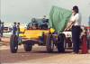
We have a rolling pan people!! Very happy with how it is sitting. But I certainly need to go up to 33s on the back. The front is a touch higher.
I just need to blow the bags up a little and put the upper bolts in.
Fitting up all the clutch and brake lines.
Pedals are all sorted.
Gearbox got new seals, caps, side adjuster locks etc.
I fitted up the handbrake and adjusted the cables. But I am not happy with the late model pivot plate on the tp of it. When you pull up on the cutting brake handles they hit it. I'm not sure if it is going to be an issue once there is pressure in the system, the handles might not come up as far. But I think I will piss it off and make something different.
And then I had to throw the body on the pan and move it out of the way to do some work on my dad's bug. I'm very happy with the way it is looking. Nice and massive!!
Anyone else's bug clear a bucket?
That's all for now everyone, thanks for reading. I'm hoping to get stuck back in after this swing of work.
Smiley |
|
| Back to top |
|
|
TDCTDI
Samba Advocatus Diaboli
Joined: August 31, 2013
Posts: 12856
Location: North Carolina
|
| Posted: Wed Oct 14, 2015 11:55 am Post subject: |
|
|
Did you really just invoke the baja bucket challenge?!? I just checked & my beam clears but not the clamps. BTW I still see some original metal on that pan, you've still got some work to do to replace it
_________________
Everybody born before 1975 has a story, good, bad, or indifferent, about a VW.
GOFUNDYOURSELF, quit asking everyone to do it for you!
An air cooled VW will make you a hoarder.
Do something, anything, to your project every day, and you will eventually complete it. |
|
| Back to top |
|
|
smileyman3000
Samba Member
Joined: November 07, 2010
Posts: 238
Location: Yeppoon, Australia
|
| Posted: Wed Oct 14, 2015 12:32 pm Post subject: |
|
|
| TDCTDI wrote: |
| Did you really just invoke the baja bucket challenge?!? I just checked & my beam clears but not the clamps. BTW I still see some original metal on that pan, you've still got some work to do to replace it |
Yep! It's a lot more fun than tipping water on your head!
And very funny! I'm not changing anything else! I sware 
Smiley |
|
| Back to top |
|
|
Outatime
Samba Member
Joined: September 23, 2015
Posts: 88
Location: MI
|
| Posted: Thu Oct 15, 2015 8:15 am Post subject: |
|
|
Very cool build, with great detailed pics.
It also burned up two hours of the workday, oops. |
|
| Back to top |
|
|
Brian
Samba Moderator

Joined: May 28, 2012
Posts: 8340
Location: Oceanside
|
|
| Back to top |
|
|
|


