| Author |
Message |
gprudenciop
Samba Member

Joined: July 06, 2008
Posts: 606
Location: portland or

|
 Posted: Fri Oct 02, 2015 12:30 pm Post subject: Posted: Fri Oct 02, 2015 12:30 pm Post subject: |
 |
|
double post
_________________
Never look down at anybody unless you are helping them up..
Loaning someone your strength instead of reminding them of their weakness = kindness.. |
|
| Back to top |
|
 |
Mavelotta
Samba Member

Joined: March 27, 2006
Posts: 50
Location: Monroe, Wa.
|
| Posted: Wed Oct 14, 2015 11:07 am Post subject: |
|
|
Your another person who could use these EFI manifolds I'm working on! I'm always a day late and a dollar short... Nice work so far Seth!
_________________
The Dub Shop
[email protected]
Facebook-Tech-Store |
|
| Back to top |
|
|
esde
Samba Member

Joined: October 20, 2007
Posts: 5969
Location: central rust belt
|
| Posted: Wed Oct 14, 2015 3:10 pm Post subject: |
|
|
Mario, I've watched your progress designing and prototyping those with great interest, no doubt they fill a void in the market. I just bought a set of the offset manifolds with injector mounts, so I'm good. Or at least I hope I am.
Question: what retains the injectors and fuel rail on the CB offset manifolds? I see no tapped hole or provision. |
|
| Back to top |
|
|
66brm
Samba Member

Joined: January 25, 2010
Posts: 3676
Location: Perth Western Australia
|
| Posted: Wed Oct 14, 2015 3:38 pm Post subject: |
|
|
Normally they are supplied with an extended stud and extra nuts, with a small bar of aluminium that pushes the rail down onto the injectors, I'll have a look and see if I have pics of mine
Actually scratch that I just saw your inj are mounted on the TB's, mine are inboard of the manifolds, so.........not sure how they are retained
_________________
Aust. RHD 66 Type 1
Aust. RHD 57 Type 1 Oval
| modok wrote: |
| I am an expert at fitting things in holes, been doing it a long time |
|
|
| Back to top |
|
|
esde
Samba Member
Joined: October 20, 2007
Posts: 5969
Location: central rust belt
|
| Posted: Wed Oct 14, 2015 6:11 pm Post subject: |
|
|
66brm, I was originally going to mount the injectors in the throttle bodies, so I wouldn't have to lose the match ported manifolds that I have. But, when I mocked it up, the slightly wider engine puts one fuel rail right against the body. I'm not comfortable with the small chance that some wheel hop could result in a high pressure fuel leak, so I stepped up to the manifolds with the inboard injector mounts. Might have a try copying the port matching that Tims did on the original manifolds.
I had to shave .5mm off the outside of the generation 3 injectors for them to seat into the manifolds. The fuel rails I had from something, and there are hold down brackets with them, but nowhere to cinch them down. Scoured the CB box, I found the mounts studs and gaskets, but nothing to help me out. If nobody has a picture of what's supposed to be I'll ping CB or Mario to ask.
SD |
|
| Back to top |
|
|
66brm
Samba Member
Joined: January 25, 2010
Posts: 3676
Location: Perth Western Australia
|
| Posted: Wed Oct 14, 2015 7:26 pm Post subject: |
|
|
http://www.noh2o.org/viewtopic.php?t=1255&postdays=0&postorder=asc&start=120
Down the page a bit is a pic of my engine with inboard injectors. The right one has the retaining tab, click on the pic for a bigger view
_________________
Aust. RHD 66 Type 1
Aust. RHD 57 Type 1 Oval
| modok wrote: |
| I am an expert at fitting things in holes, been doing it a long time |
|
|
| Back to top |
|
|
esde
Samba Member
Joined: October 20, 2007
Posts: 5969
Location: central rust belt
|
| Posted: Wed Oct 14, 2015 7:44 pm Post subject: |
|
|
Thanks! OK, I can make that happen, it's about as simple as it gets huh?
Is that a valve on the drivers side rail for checking pressure? |
|
| Back to top |
|
|
Mavelotta
Samba Member
Joined: March 27, 2006
Posts: 50
Location: Monroe, Wa.
|
| Posted: Wed Oct 14, 2015 7:56 pm Post subject: |
|
|
| esde wrote: |
| Question: what retains the injectors and fuel rail on the CB offset manifolds? I see no tapped hole or provision. |
Here is CB's solution
Here is my solution
_________________
The Dub Shop
[email protected]
Facebook-Tech-Store |
|
| Back to top |
|
|
66brm
Samba Member
Joined: January 25, 2010
Posts: 3676
Location: Perth Western Australia
|
| Posted: Wed Oct 14, 2015 7:59 pm Post subject: |
|
|
Yeah its just a shrader valve tapped into a 1/8 npt thread, I've been thinking of putting a gauge there to monitor rail pressure (oh and that's the passenger side  ) )
_________________
Aust. RHD 66 Type 1
Aust. RHD 57 Type 1 Oval
| modok wrote: |
| I am an expert at fitting things in holes, been doing it a long time |
|
|
| Back to top |
|
|
Singerdude
Samba Member
Joined: March 07, 2015
Posts: 464
Location: Quebec, Canada
|
| Posted: Wed Oct 14, 2015 11:16 pm Post subject: |
|
|
| Kudos on the FI setup esde, one day Perhaps... Right now my carbs are new and the next 3 year's budget is already spent... |
|
| Back to top |
|
|
esde
Samba Member
Joined: October 20, 2007
Posts: 5969
Location: central rust belt
|
| Posted: Thu Nov 12, 2015 10:01 pm Post subject: Re: Megasquirt 2 system assembly and installation |
|
|
Slow progress, as I've got 10 projects in the fire at once. And the engine was apart, so I had no way of going any farther with the wiring harness. But, finally stuff is happening again.
So, I did have a shot at porting the intake manifolds to match the Tims stage 2 heads
It went pretty smoothly after I got some fresh carbide burrs and a few 60 grit tapered cartridge rolls. Still a little touch up to go, but it matches the heads pretty closely
Spent some time getting the pickup for the trigger wheel mounted. Here I tried to mount the pickup behind the bracket, but then I had to slide it way out to meet the pulley, and it was barely under the nut.
So I flipped the pickup to the front of the bracket. It's adjustable, but I had to trim the back of the bracket so it would sit closer to the case. If I had taken a deeper cut out of the pulley for the trigger wheel there would've been more room. But, sinking the wheel deeper in the pulley also limits the thread of the screws that fasten the wheel. I played it safe.
And got on to the wiring harness
I had assembled the wires to their plugs previously. Next was to route them, so I mocked up each side of the engine.
The CB short manifolds don't make it easy, this wire has to sneak out through the middle of the manifold
And the when the lengths were good, feed it through some larger loom, and shrink wrap the ends.
I've held off on the other side, as I'm not 100% on my coil location. Pretty sure that top center of the rear of the shroud, (front actually  ) as it's just out of sight, but I'll be able to reach the wires. ) as it's just out of sight, but I'll be able to reach the wires.
Also contemplating a bulkhead plug, to disconnect the whole harness, but not sure I feel like crimping another 40-50 connections. We'll see, it would maybe be a convenience, but I certainly don't need it.
SD |
|
| Back to top |
|
|
esde
Samba Member
Joined: October 20, 2007
Posts: 5969
Location: central rust belt
|
| Posted: Fri Nov 13, 2015 8:28 pm Post subject: Re: Megasquirt 2 system assembly and installation |
|
|
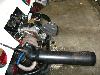
Time for a little advice. I had the intention of switching from the scat doghouse shroud to a stock doghouse, and installing a larger type 4 oil cooler. Here it is, in all of it's filthy glory. Bonus, the new sidewinder header clears the thermostat so I can hook the flaps up too..
a peek at how much larger the type 4 cooler is
I have seen first hand the drop in oil temperature when switching back to an original factory doghouse shroud, and when using the larger type 4 cooler. So I'm confident it will help to keep the temps in check, before it was right on the edge..
Of course this has nothing to do with the fuel injection installation except for this
So, the fuel rail and shroud want to occupy the same space. Kind of a bummer, but I'm already planning to modify the shroud to make it work.
I'm not running heat (car has a gas heater for when I need to defog the windows) so the plan is to cut and cap the left and right outlets. Then I will trim the protruding corners. Imagine a cut line along the cardboard I've held up here
One each side of the shroud, the farthest vane feeds the heater box outlet. As long as I open this vane back to the cylinder head (on each side) I won't have any air fighting a dead end, and have full cooling.
So, what am I missing? Is this the long way about it, or is there a better shroud option?
SD |
|
| Back to top |
|
|
clonebug
Samba Member
Joined: January 29, 2005
Posts: 4027
Location: NW Washington
|
| Posted: Sat Nov 14, 2015 8:11 am Post subject: Re: Megasquirt 2 system assembly and installation |
|
|
| esde wrote: |
Slow progress, as I've got 10 projects in the fire at once. And the engine was apart, so I had no way of going any farther with the wiring harness. But, finally stuff is happening again.
So, I did have a shot at porting the intake manifolds to match the Tims stage 2 heads
It went pretty smoothly after I got some fresh carbide burrs and a few 60 grit tapered cartridge rolls. Still a little touch up to go, but it matches the heads pretty closely
Spent some time getting the pickup for the trigger wheel mounted. Here I tried to mount the pickup behind the bracket, but then I had to slide it way out to meet the pulley, and it was barely under the nut.
So I flipped the pickup to the front of the bracket. It's adjustable, but I had to trim the back of the bracket so it would sit closer to the case. If I had taken a deeper cut out of the pulley for the trigger wheel there would've been more room. But, sinking the wheel deeper in the pulley also limits the thread of the screws that fasten the wheel. I played it safe.
And got on to the wiring harness
I had assembled the wires to their plugs previously. Next was to route them, so I mocked up each side of the engine.
The CB short manifolds don't make it easy, this wire has to sneak out through the middle of the manifold
And the when the lengths were good, feed it through some larger loom, and shrink wrap the ends.
I've held off on the other side, as I'm not 100% on my coil location. Pretty sure that top center of the rear of the shroud, (front actually ) as it's just out of sight, but I'll be able to reach the wires.
Also contemplating a bulkhead plug, to disconnect the whole harness, but not sure I feel like crimping another 40-50 connections. We'll see, it would maybe be a convenience, but I certainly don't need it.
SD |
If I remember correctly some have trimmed the bottom of the two ends of the fuel rail at a 45 degree to give enough room for the plugs to connect to the injectors so they are parallel with the fuel rail....if you can understand what I mean.
If you look at Mario's pic in your thread you can see with his endpieces the injectors are turned and have clearance.
It might be easier to get his endpieces otherwise instead of butchering a shroud.
I'm pretty sure there is enough meat on the CB rails to trim enough to get them turned.
_________________
| vwracerdave wrote: |
Take a good long look in the mirror and report back on what you see. |
| Paul.H wrote: |
| That one line on that chart is probably better info than you can get from this place in a month |
My Megasquirt Fuel Injection Turbo Buggy Build
Water/Alcohol Injection
Audi TT intercooler
Upgraded to MS3Pro-Evo
EcuMaster PMU16
ECUMaster ADU5 Digital Dash
http://www.shoptalkforums.com/viewtopic.php?f=3&t=127936 |
|
| Back to top |
|
|
esde
Samba Member
Joined: October 20, 2007
Posts: 5969
Location: central rust belt
|
| Posted: Sat Nov 14, 2015 11:00 am Post subject: Re: Megasquirt 2 system assembly and installation |
|
|
Clonebug, no doubt the other manifolds and/or rails would solve the issue. It seems that every picture of the cb manifolds with inboard injectors is using a 36hp style shroud, now I know why. But I already have these, and a small pile of doghouse shrouds to work with. So, I'll see if there's another way..
Honestly doesn't seem like much work, and I'm already committed to welding a shroud for the larger cooler, so..
Probably get started on it tomorrow when the family is out. |
|
| Back to top |
|
|
clonebug
Samba Member
Joined: January 29, 2005
Posts: 4027
Location: NW Washington
|
| Posted: Sat Nov 14, 2015 1:04 pm Post subject: Re: Megasquirt 2 system assembly and installation |
|
|
I would bet you would only have to take a little bit off those fuel rails to make enough clearance.
If you did that you wouldn't have to run that injector wire between the intake manifold forcing you to pull a TB in order to remove the wiring.
I don't know how much time I spent trying to route my wires so I could remove it without disassembling half the engine to get it out........ 
_________________
| vwracerdave wrote: |
Take a good long look in the mirror and report back on what you see. |
| Paul.H wrote: |
| That one line on that chart is probably better info than you can get from this place in a month |
My Megasquirt Fuel Injection Turbo Buggy Build
Water/Alcohol Injection
Audi TT intercooler
Upgraded to MS3Pro-Evo
EcuMaster PMU16
ECUMaster ADU5 Digital Dash
http://www.shoptalkforums.com/viewtopic.php?f=3&t=127936 |
|
| Back to top |
|
|
esde
Samba Member
Joined: October 20, 2007
Posts: 5969
Location: central rust belt
|
| Posted: Sat Nov 14, 2015 2:00 pm Post subject: Re: Megasquirt 2 system assembly and installation |
|
|
| Ok, I went down to my bench, and see what you are talking about. Trimming the end of the rail will probably allow me to swing that injector to the rear and make the connector access easier. Thanks for the tip. However, the shroud still needs to be neutered. My picture doesn't show it very well, but the injector and rail are pushed over to the outside by that part of the shroud. I read some more about modifying the shroud last night, and am pretty confident that it is going to work out. |
|
| Back to top |
|
|
esde
Samba Member
Joined: October 20, 2007
Posts: 5969
Location: central rust belt
|
| Posted: Mon Nov 16, 2015 5:53 pm Post subject: Re: Megasquirt 2 system assembly and installation |
|
|
Got to work on the shroud. Here's what was removed
You can see that this is the "vane" that supplies air to the heater boxes. I opened it back up so it will blow at the cylinder heads.
And capped it, needs final welding
And while I was at it, welded the extension to cover the type 4 cooler
Now that I'm sure it fits, I can finish it and continue with the install..
SD |
|
| Back to top |
|
|
esde
Samba Member
Joined: October 20, 2007
Posts: 5969
Location: central rust belt
|
| Posted: Tue Nov 17, 2015 8:21 pm Post subject: Re: Megasquirt 2 system assembly and installation |
|
|
| clonebug wrote: |
If I remember correctly some have trimmed the bottom of the two ends of the fuel rail at a 45 degree to give enough room for the plugs to connect to the injectors so they are parallel with the fuel rail....if you can understand what I mean.
I'm pretty sure there is enough meat on the CB rails to trim enough to get them turned. |
Clonebug, thanks for the thought, it seems to have worked out pretty well. A 45º cut wasn't quite enough, so I ground a small radius.
Because of the offset manifolds, I only have to do one edge of each fuel rail. It barely fits, but it does.
I have to decide how to route the fuel line that connects the rails so that it doesn't interfere with the flap linkage bar, and get some nut serts to mount the wasted spark coil to the shroud..
SD |
|
| Back to top |
|
|
esde
Samba Member
Joined: October 20, 2007
Posts: 5969
Location: central rust belt
|
| Posted: Tue Nov 17, 2015 8:22 pm Post subject: Re: Megasquirt 2 system assembly and installation |
|
|
edit dup post
Last edited by esde on Tue Nov 17, 2015 8:53 pm; edited 1 time in total |
|
| Back to top |
|
|
clonebug
Samba Member
Joined: January 29, 2005
Posts: 4027
Location: NW Washington
|
| Posted: Tue Nov 17, 2015 8:50 pm Post subject: Re: Megasquirt 2 system assembly and installation |
|
|
Very Nice!!!!
Glad I could help....
That is pretty well exactly what the fuel rail I saw that was modified looked like!!!!
| esde wrote: |
| clonebug wrote: |
If I remember correctly some have trimmed the bottom of the two ends of the fuel rail at a 45 degree to give enough room for the plugs to connect to the injectors so they are parallel with the fuel rail....if you can understand what I mean.
I'm pretty sure there is enough meat on the CB rails to trim enough to get them turned. |
Clonebug, thanks for the thought, it seems to have worked out pretty well. A 45º cut wasn't quite enough, so I ground a small radius.
Because of the offset manifolds, I only have to do one edge of each fuel rail. It barely fits, but it does. |
_________________
| vwracerdave wrote: |
Take a good long look in the mirror and report back on what you see. |
| Paul.H wrote: |
| That one line on that chart is probably better info than you can get from this place in a month |
My Megasquirt Fuel Injection Turbo Buggy Build
Water/Alcohol Injection
Audi TT intercooler
Upgraded to MS3Pro-Evo
EcuMaster PMU16
ECUMaster ADU5 Digital Dash
http://www.shoptalkforums.com/viewtopic.php?f=3&t=127936 |
|
| Back to top |
|
|
|


