| Author |
Message |
nlorntson
Crazy VW Lady
Joined: March 13, 2004
Posts: 3783
Location: Twin Cities, MN

|
 Posted: Thu Jan 21, 2016 10:32 am Post subject: 1963 Double cab electronics restoration Posted: Thu Jan 21, 2016 10:32 am Post subject: 1963 Double cab electronics restoration |
 |
|
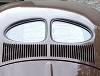
I thought I'd try to collect all my work getting the electronics for our 1963 DC bench tested, all in one place. This truck will be brought back to it's original 6V configuration.
I'm trying to go through and leave as much as possible alone, but I want it to all work, so cleaning and polishing and only soldering where absolutely necessary.
I'll start with the fuel gauge and sender.
fuel gauge and sender
Here is the testing and repair of my fuel gauge and tank sender for my April 1963 DC. Based on the dates, these appear to be the originals for the truck.
The PO had done a half hearted 12V conversion and one of the wires to the fuel gauge had fried to a crisp so I was not hopeful that the gauge would work.
Also, the truck had sat 1/2 to 2/3 full of gasoline for 20+ years. It probably saved the tank which is shiny silver inside, but it was really nasty stuff after 20 years and gummed up the sender so it was not functional.
Following an excellent post in the bay forum (http://www.thesamba.com/vw/forum/viewtopic.php?t=629435) I was able to disassemble the sender.
Sure enough the contact between the top and the brass tensioner piece was gone.
The repair in the bay forum shows drilling a hole in the top and soldering a wire onto the brass piece. I could not bring myself to drilling that hole so I opted for making the solder connection directly. I cleaned and cleaned and cleaned both areas with a variety of tools, scrapers, files, sand paper, until it shined.
I then put a blob of solder in the corner. Ohms measured zero now between the lid and the tensioner.
I checked the Ohms with the float all the way up like a full tank, and down like and empty tank. The values were slightly different than the bay window post said but the same when I checked by contacting the lid and brass piece with the probes prior to soldering. I did the solder on both sides of the rivet (belt and suspenders). If you go this route, be sure to leave room for the sender housing to fit. I guess if my solder joints fail, I'll be pulling the sender but in a DC it's a little less difficult to do so I'm taking my changes with this repair.
Fuel Gauge
For the gauge, I hooked it up as shown and applied 6V, and much to my surprise it worked!
Green wire grounds the G to the body of the sender and to the negative of the 6V power supply.
Red wire connects the "+" on the gauge to the 6V power supply. When you touch the red wire to the power supply, the needle should snap over to Full.
I cleaned up the rest of the gauge, added a brand new 6V bulb and holder and we're good to go!
Moving across the dash is the emergency flasher indicator light.
Emergency Flasher Indicator
This is a very simple light that unscrews for removal. If the red lense needs to come out, there is a snap ring that holds it in. When this indicator is installed, it is important that there is a good connection on the back side of the dash between the light and the truck so the bulb will have a proper ground and light up.
Mine just needed a good cleaning of the bulb holder, light base and chrome surround, plus a new light bulb.
Next is the wiper switch
Wiper Switch
This is a very simple switch that controls the single speed wipers. Wipers are either on or off.
There should be no current flowing (1.00) between the terminals when the switch is pushed in and zero ohms (0.00) when it is out.
Mine checked out so I cleaned the switch,terminals, and screw, and polshed up the aluminum bezel.
Next is the Emergency flasher switch.
Emergency Flasher Switch
This is also either on or off. There should be no current flowing (1.00) between the terminals when the switch is pushed in and zero ohms (0.00) when it is out. I imagine there is a lot of current flowing through this when the flashers are on.
Mine checked out with the ohm meter so I cleaned the switch body,terminals, and screw, and polshed up the aluminum bezel.
Ignition switch
As far as I know, mine was working fine so I did not disassemble it other than to rekey the lock cylinder. They can be completely disassembled but it aint broke as they say.
Testing wise I checked for resistance between terminals with the key in various positions.
KEY 1st click (running position)
30 --> 15/54 = 0 ohms (closed circuit)
All other combinations were 1.0 (open circuit)
KEY 2nd click (starting position)
30 --> 50 = 0
30 --> 15/54 = 0
50 --> 15/54 = 0
A lot of current runs through this switch so it needs to be firmly mounted and terminals should be really clean for quick, full power starts.
I have the headlight switch and flasher relay to test and clean up. I'll edit this post to add them in a bit. |
|
| Back to top |
|
 |
easy e
Samba Member
Joined: May 28, 2008
Posts: 3931
Location: 1 hr north of Santa Barbara
|
|
| Back to top |
|
|
1967250s
Samba Member
Joined: May 02, 2007
Posts: 2137
|
| Posted: Thu Jan 21, 2016 11:23 am Post subject: Re: 1963 Double cab electronics restoration |
|
|
Nice write up. I would caution others on the fuel sender though: the solder should NOT touch the through rivet, just the cap and large tensioning ring. When soldering in a tight area like this where there are other solder joints- protect the other joints with some type of heat shield, maybe wrap a small(tiny) piece of wet cloth around the solder, or attach a small clip to be a heat sink. Can you tell us the cleaners and polish you used?
_________________
'72 Elm Green Deluxe |
|
| Back to top |
|
|
EverettB 
Administrator
Joined: April 11, 2000
Posts: 69823
Location: Phoenix Metro
|
|
| Back to top |
|
|
nlorntson
Crazy VW Lady
Joined: March 13, 2004
Posts: 3783
Location: Twin Cities, MN
|
| Posted: Fri Jan 22, 2016 6:31 am Post subject: Re: 1963 Double cab electronics restoration |
|
|
| EverettB wrote: |
| Nice breakdown, I am surprised your ignition had no resistance as-is. |
Why is that? |
|
| Back to top |
|
|
EverettB
Administrator
Joined: April 11, 2000
Posts: 69823
Location: Phoenix Metro
|
| Posted: Fri Jan 22, 2016 8:23 am Post subject: Re: 1963 Double cab electronics restoration |
|
|
| nlorntson wrote: |
| EverettB wrote: |
| Nice breakdown, I am surprised your ignition had no resistance as-is. |
Why is that? |
The ones I have tested usually had some minor resistance on the Ohm meter when tested. Dirty or worn inside I guess.
A lot of times it was just dirty terminals on the outside though.
I haven't tested that many so I wouldn't take this as a rule.
Headlight switches are usually the worst for this though.
_________________
How to Post Photos
Everett Barnes - [email protected] | My wanted ads
"Water is the only drink for a wise man" | "Communication prevents complaints"
Stop dead photo links! Post your photos to The Samba Gallery! |
|
| Back to top |
|
|
nlorntson
Crazy VW Lady
Joined: March 13, 2004
Posts: 3783
Location: Twin Cities, MN
|
| Posted: Sun Jan 24, 2016 10:48 am Post subject: Re: 1963 Double cab electronics restoration |
|
|
Headlight switch
Tested ok with a 6V load so I'm going to try as is. If it gets hot, I'll disassemble and solder the contacts inside.
Someone asked what I used to clean these up. I used a combination of several wire wheels on my dremel mostly.
For polishing the housings, I used the wire wheels and then a "scotchbrite" wheel and finally a buffer wheel with some Autosol metal polish.
For the knobs, I used a piece of brass stock and cut threads in to the end. The headlight takes a bigger size than the other knobs. I chucked it up in a drill and screwed the knob on the end used some gritty hand cleaner to get the initial dirt off, then I used the Autosol polish on a soft cloth to finish the rest. The knobs went from a flat brown to a shiny black.
Next will be the turn signal.
Last edited by nlorntson on Fri Feb 05, 2016 9:56 pm; edited 1 time in total |
|
| Back to top |
|
|
nlorntson
Crazy VW Lady
Joined: March 13, 2004
Posts: 3783
Location: Twin Cities, MN
|
| Posted: Wed Feb 03, 2016 11:47 am Post subject: Re: 1963 Double cab electronics restoration |
|
|
This truck has a 6 wire turn signal switch. I did some testing of it prior to taking it apart and discovered a problem so I took it apart and found a broken wire
I'll have to solder in a new piece of solid core wire it looks like.
I'll also add some di-electric grease to the mechanical portion. |
|
| Back to top |
|
|
nlorntson
Crazy VW Lady
Joined: March 13, 2004
Posts: 3783
Location: Twin Cities, MN
|
| Posted: Wed Feb 03, 2016 9:56 pm Post subject: Re: 1963 Double cab electronics restoration |
|
|
Small wire was repaired and the the green/white/black was soldered a bit more too. Signal mechanics were lubricated and tested.
Connections on the wire ends were cleaned up with a wire wheel on a dremel.
Knob was cleaned up
Pieces were organized
Finished product
|
|
| Back to top |
|
|
BarryL
Samba Member
Joined: November 01, 2004
Posts: 14266
Location: Casa de Oro, California
|
| Posted: Thu Feb 04, 2016 9:26 am Post subject: Re: 1963 Double cab electronics restoration |
|
|
| I like how you hunted down the broken wire. It looks to have been shorted and burned on my screen. |
|
| Back to top |
|
|
nlorntson
Crazy VW Lady
Joined: March 13, 2004
Posts: 3783
Location: Twin Cities, MN
|
| Posted: Thu Feb 04, 2016 9:50 am Post subject: Re: 1963 Double cab electronics restoration |
|
|
| BarryL wrote: |
| I like how you hunted down the broken wire. It looks to have been shorted and burned on my screen. |
Thanks BarryL
It may have been shorted as the PO had done a half a$$ conversion to 12V but things like some of the bulbs and emergency flasher relay were still 6V
It's my hope that by testing and fixing now I'll be able to just install and connect all these pieces and not have to hunt down electrical gremlins later.
The one thing I have left to do is test that flasher relay but I need to find one more bulb holder for my second 18W bulb. I'm trying to make some bench testing "tools" so future testing is mostly plug and play. |
|
| Back to top |
|
|
nlorntson
Crazy VW Lady
Joined: March 13, 2004
Posts: 3783
Location: Twin Cities, MN
|
| Posted: Fri Feb 05, 2016 9:45 pm Post subject: Re: 1963 Double cab electronics restoration |
|
|
This DC is an April 1963 1 Ton DC with the red emergency flasher indicator light to the left of the speedo and above the wiper switch.
The original wiring for this indicator light is via a gray wire that runs from terminal 86 on the flasher relay to one of the four connectors on the switch and then onto the bulb for the light. The wire is a single gray wire between the relay and switch but a double wire coming off the switch.
The Wolfsburg West wiring kit choice is either 60-63 or 1963-1964 (fits these years with voltage regulator located remotely) . I opted for the 63 -64 version hoping it would be closer to what need than the 60-63. The 63-64 kit has the indicator wire as a red wire and it only goes between the flasher relay and the switch. The extra wire is not shown in the instructions for the emergency flasher circuit. To wire up the emergency flasher indicator light you'll need to add a piggyback connector to the switch and run a single wire over to the light, or cut off the WW connector and crimp on a new connector with the extra wire.
My original harness appears to be in pretty good shape so I may just clean it up and use that.
The light gray (or dirty white) wire in the pictures is the wire.
Flasher relay. gray wire comes off the flasher relay and heads to the switch:
From the switch, it's now a double wire connection it heads over to the light
And a single wire from the switch to the light
|
|
| Back to top |
|
|
nlorntson
Crazy VW Lady
Joined: March 13, 2004
Posts: 3783
Location: Twin Cities, MN
|
| Posted: Sun Feb 07, 2016 4:23 pm Post subject: Re: 1963 Double cab electronics restoration |
|
|
I'm nearly done restoring all these pieces.
I got the flasher tested and it works albeit slowly so I may keep an eye out for another one.
Per the advice of a couple of others, I soldered the joints in the fuse box to help reduce some of the resistance there.
|
|
| Back to top |
|
|
nlorntson
Crazy VW Lady
Joined: March 13, 2004
Posts: 3783
Location: Twin Cities, MN
|
| Posted: Sat Jun 25, 2016 1:25 pm Post subject: Re: 1963 Double cab electronics restoration |
|
|
A frustratingly long wait for the body to return from the paint shop so I'm still plugging away on getting other things organized for the reassembly. The inside, engine compartment, and underneith is painted, now just waiting on final primer and sanding for the outer body, gates and doors.
I though I'd add a bit more to the electronics list. I restored the speedometer including the oil, generator, high beam, and turn signal light gels, and the speedometer illumination. That post is here:
SPEEDOMETER RESTORATION
http://www.thesamba.com/vw/forum/viewtopic.php?t=646343
I wanted to make a list of the bulbs needed for the truck, and maybe this will help out someone else. It's a US delivery truck and I'm going with the stock 6V incandescent lamps throughout. Here's a list of those lamps (please let me know of any corrections).
Headlights low/high beam (2) - #6006 6.1/6.2V 40/50W Base: PAR56 7" Round Sealed Beam
I also considered a Halogen version (6006H H4 headlamp 60/55w 6V bulb) for a brighter headlight, but the increased wattage going through the headlight switch may be a problem unless I take the switch apart, clean up the internals and solder terminals as suggested. For now I'll try the lower wattage and see how all that goes. It's easy enough to swap them out later.
Parking lights (2) - #63 6V, 4W, .63A, Base: BA15s G6
Turn signals (2) - #1129 6.4V, 16.832W, 2.63A, Base: BA15s s8
Speedometer lights (6) - #3799 6V, 1.2W, 0.2A, Base: BA7s
Emergency flasher indicator (1) - #3799 6V, 1.2W, 0.2A, Base: BA7s
Fuel Gauge light (1) - #3799 - 6V, 1.2W, 0.2A, Base: BA7s
Dome light (2) - #6416 6V, 5W, .83A, Festoon
Rear brake light/tail light/signal (2) - #1154 6.4V, 16.6/5.2 Watts, 2.63A/.75A, Base: BA15d
If using a two bulb housing, Tail light (2) - #1129 6.4V, 16.832W, 2.63A, Base: BA15s |
|
| Back to top |
|
|
cru62
Samba Member

Joined: December 31, 2002
Posts: 4117
Location: Margaritaville.....24/7
|
| Posted: Sat Jun 25, 2016 6:12 pm Post subject: Re: 1963 Double cab electronics restoration |
|
|
Nancy-Since the most important part of the terminal end on the wires is almost impossible to clean well, I have used both vinegar and catsup/ketchup to clean the brass. I have also used it to soak my fuse block in to remove the green corrosion inside the block where the two pieces of the circuit touch. I have also taken the blocks apart to clean them. But the last one I did was brittle and a small chunk broke off, so I don't do that any more.
Thanks for the tutorial.
_________________
"My biggest worry is that when I die, my wife will sell all my parts for what I told her I paid for them"-Jon
Jokes about German sausage are the wurst.
Stop dead photo links! Post your photos to The Samba Gallery! |
|
| Back to top |
|
|
nlorntson
Crazy VW Lady
Joined: March 13, 2004
Posts: 3783
Location: Twin Cities, MN
|
| Posted: Sat Jun 25, 2016 7:24 pm Post subject: Re: 1963 Double cab electronics restoration |
|
|
| cru62 wrote: |
Thanks for the tutorial. |
Thanks for the suggestion! |
|
| Back to top |
|
|
BarryL
Samba Member
Joined: November 01, 2004
Posts: 14266
Location: Casa de Oro, California
|
| Posted: Sun Jun 26, 2016 9:14 am Post subject: Re: 1963 Double cab electronics restoration |
|
|
| nlorntson wrote: |
| ...6006H H4 headlamp 60/55w 6V bulb) for a brighter headlight, but the increased wattage going through the headlight switch may be a problem... |
This is the set up I have. My wire ends are soldered as well as the fuse block. The switch is stock. The wire leaving the switch gets hot right at the spade but that is all. Works perfect. |
|
| Back to top |
|
|
nlorntson
Crazy VW Lady
Joined: March 13, 2004
Posts: 3783
Location: Twin Cities, MN
|
| Posted: Sun Jun 26, 2016 12:27 pm Post subject: Re: 1963 Double cab electronics restoration |
|
|
| BarryL wrote: |
| My wire ends are soldered |
I'm using a brand new wiring harness. Where are you recommending the solder be? Between the spade connector and the copper strands at the crimp? |
|
| Back to top |
|
|
BarryL
Samba Member
Joined: November 01, 2004
Posts: 14266
Location: Casa de Oro, California
|
| Posted: Sun Jun 26, 2016 6:49 pm Post subject: Re: 1963 Double cab electronics restoration |
|
|
| nlorntson wrote: |
| BarryL wrote: |
| My wire ends are soldered |
I'm using a brand new wiring harness. Where are you recommending the solder be? Between the spade connector and the copper strands at the crimp? |
Yes. I touch the iron to the back of the spade then let the solder touch right at the cross section of wire and it flows back into the wire and crimp. |
|
| Back to top |
|
|
ToolBox
Samba Member

Joined: January 27, 2004
Posts: 3439
Location: Detroit, where they don't jack parts off my ride in the parking lot of the 7-11
|
| Posted: Mon Jun 27, 2016 9:45 am Post subject: Re: 1963 Double cab electronics restoration |
|
|
| nlorntson wrote: |
Headlights low/high beam (2) - #6006 6.1/6.2V 40/50W Base: PAR56 7" Round Sealed Beam
I also considered a Halogen version (6006H H4 headlamp 60/55w 6V bulb) for a brighter headlight, but the increased wattage going through the headlight switch may be a problem unless I take the switch apart, clean up the internals and solder terminals as suggested. For now I'll try the lower wattage and see how all that goes. It's easy enough to swap them out later. |
.
The stock lights will be better if you service the switch also. |
|
| Back to top |
|
|
|


