| Author |
Message |
electricolive
Samba Member
Joined: April 20, 2013
Posts: 14
Location: Berwyn PA

|
 Posted: Sun May 14, 2023 10:59 am Post subject: Isetta EV Hot Rod Build Posted: Sun May 14, 2023 10:59 am Post subject: Isetta EV Hot Rod Build |
 |
|
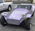
The build threads and other posts here are inspiring. Here is a mock up of my latest project. I am using a 1973 Super Beetle as a starting point for the chassis and I have two BMW Isetta bodies that are in pretty rough condition - what could possibly go wrong...
_________________
Check out the video of Olive here: https://www.youtube.com/watch?v=L54eqGnPGRI&ab_channel=MonolithMotors |
|
| Back to top |
|
 |
vwuberalles
Samba Member

Joined: October 18, 2003
Posts: 1357
Location: Richmond, VA
|
|
| Back to top |
|
|
EVfun
Samba Member
Joined: April 01, 2012
Posts: 5474
Location: Seattle
|
| Posted: Thu May 18, 2023 3:10 pm Post subject: Re: Isetta EV Hot Rod Build |
|
|
Nice motor! Looks somewhat familiar
_________________
| Wildthings wrote: |
| As a general rule, cheap parts are the most expensive parts you can buy. |
|
|
| Back to top |
|
|
electricolive
Samba Member
Joined: April 20, 2013
Posts: 14
Location: Berwyn PA
|
| Posted: Sat May 20, 2023 4:49 pm Post subject: Re: Isetta EV Hot Rod Build |
|
|
Sweet Dune Buggy, EVfun. Here is some background on the project. The Super Beetle chassis is actually from the first car I ever owned - a 1973 Calypso Green just like VWuberalles! I got it in trade for painting a friends car. It ran but the rockers were completely rusted out. I effected some crude repairs and an obligatory 80's red and black wedge paint scheme. I had the car for years, sold it then bought it back with a blown engine and bent frame head. It sat around for several years until I came up with the idea to put a stretched Isetta body on the chassis.
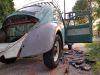
Here is the Super before getting chopped up. I kept alot of the sheetmetal and some of it will wind up in the Isetta body.
Front suspension was not going to work with the Isetta so I liberated in from the the rest of the chassis.
There was alot of surface rust and some parts near the torsion tube rusted away.
Sand blasted to remove rust and painted the bottom side - the floorpans and most the structure are suprisingly solid.
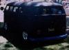
Here are two Isettas that I bought for the project. I bought the 'red' one in 2010 for $700. It had been lovingly restored and, when finishing the interior, the seat frame touched both battery terminals and the resulting fire warped most of the sheetmetal. Hope to make something good from that sad story.
I cut the red Isetta up first to help with the mock up.
The green Isetta had been sitting in a field near Reading Pa for decades when I bought it in 2003 for $300. A tree fell on it in 1973. This is the 'good' car that I hope to use for most of the body.
I did some initial work on the chassis and Isettas back in 2012. The mock up showed that I needed a much wider track, so I bought some 3x3" extended trailing arms. I realized this project was beyond my capabilities to put together and I set the dream aside. So 10 years later and with a bit more fabrication experience under my belt, I am ready to make this thing happen...
_________________
Check out the video of Olive here: https://www.youtube.com/watch?v=L54eqGnPGRI&ab_channel=MonolithMotors |
|
| Back to top |
|
|
electricolive
Samba Member
Joined: April 20, 2013
Posts: 14
Location: Berwyn PA
|
| Posted: Mon May 29, 2023 4:45 pm Post subject: Re: Isetta EV Hot Rod Build |
|
|
Here is a pic of the NetGain Hyper9 AC motor that I bought from EV West. It is a high efficiency, permanent magnet assisted synchronous reluctance design with 88KW max power and 173 lb/ft of torque. Plan to have the transmission rebuilt as a 2 speed.
I want the motor to be visually more proportional to the size of the car, so I purchased a cheap industrial motor off ebay. I will use its finned housing to fit over the NetGain motor. The industrial motor has a 13" OD compared to the 8.5" OD of the NetGain. Will connect them with aluminum blocks so the additional heat sink helps rather that hurts the heat transfer from the NetGain.
I had fun figuring out how to take it apart. Will either have to cut or heat up the housing to get the stator laminations and windings out - that is a problem for future Bob.
Also recently cut up the green Isetta. It had become mouse infested after years of sitting in my shed - took some cleaning to get the nests and smell out.
I sliced it the opposite way from the red one - after adding some bracing (white tubes). This cut will work out better to keep the side body lines. Will add some metal at the center of the back to widen and metal at the front of the sides to lengthen.
That catches us up to present day. After way too much deliberation, I picked a direction for the front suspension. I have most of that on order now and will buy some square and round tube to finish building a frame table and start the frame fabrication...
_________________
Check out the video of Olive here: https://www.youtube.com/watch?v=L54eqGnPGRI&ab_channel=MonolithMotors |
|
| Back to top |
|
|
EVfun
Samba Member
Joined: April 01, 2012
Posts: 5474
Location: Seattle
|
| Posted: Mon May 29, 2023 5:42 pm Post subject: Re: Isetta EV Hot Rod Build |
|
|
This is looking interesting... I'm having some trouble following your direction toward the goals but that only adds to my fascination with your project. The idea you need a bigger electric motor -- that gives me a chuckle.
When I built my EV buggy back in 1999 it got all kinds of comments. Most wondered what gas turbine I put into the buggy. Next was questions about where IS the engine. Lastly, a few recognized my old school Prestolite MTC DC motor. Sadly, about half of them asked if I had thought to put a generator on the wheels to keep the battery pack continuously charged. 
I am now of converting it back into a VW powered buggy. After 20 years as an EV the questions changed. Almost everyone recognizes it's an EV and then starting asking about the range. Since I didn't want to make a bloated ride of batteries (and they are hard to hide on a beach buggy) I had a small pack. It was 128 volt Lithium Iron Phosphate pack with 60 amp hours capacity, just 195 pounds of batteries in about a 10.5 gallon space where the gas tank would have been. I had about 7.5 kWh of power and with the poor aerodynamics the best I could do was about a 30 mile range at 60 mph. Yeah, typical range was about 30 miles. I could demonstrate a low speed urban cycle and show a 50 mile range but I couldn't honestly quote that.
_________________
| Wildthings wrote: |
| As a general rule, cheap parts are the most expensive parts you can buy. |
|
|
| Back to top |
|
|
Buggeee
Samba Member
Joined: December 22, 2016
Posts: 4407
Location: Stuck in Ohio
|
|
| Back to top |
|
|
finster
Samba Member

Joined: May 26, 2012
Posts: 7935
Location: north o' the border
|
| Posted: Mon Jun 12, 2023 8:46 am Post subject: Re: Isetta EV Hot Rod Build |
|
|
a brilliant concept, so refreshing to see a different shape! 
_________________
"we're here on Earth to fart around" kurt vonnegut
nothing lasts, nothing is finished, and nothing is perfect... |
|
| Back to top |
|
|
electricolive
Samba Member
Joined: April 20, 2013
Posts: 14
Location: Berwyn PA
|
| Posted: Tue Jun 20, 2023 2:26 pm Post subject: Re: Isetta EV Hot Rod Build |
|
|
Thanks for all the great comments - I do admit to going overboard with the enhanced electric motor heat sink. I am going with size does matter here to make the proportions look right at the back of the car. I did not like the idea of cutting the heat sink to get it off the stator - I was not sure I could get a clean and even cut down the length of it. I figured maybe I could heat the whole thing up and expand the aluminum part and remove the steel laminations and copper windings. I did some craigslist shopping for an outdoor boiler and a propane tank and bought a steel trash can at Home Depot for an improvised oven.
I heated the motor for 30 minutes...
And was able to push the stator out with a dozen or so whacks with a sledgehammer all without burning my neighbor or myself on the seriously hot metal.
And here is the larger heat sink fit over the motor - that look is worth the effort.
So now that the mock up phase is mostly done, it is time to get serious and sort out the chassis design details. I am still waiting for the front suspension parts that I ordered, so I am starting on the rear suspension. I read alot of the helpful post in the HBB Off-Road forum about the steps required to set up the 3x3 trailing arms.
I tried to fit the axle shaft in between the transmission flange and stub axle flange to start looking at suspension travel and CV angles and they did not fit unless the trailing arms were extended way down. I checked the rear toe which was way off and adjusted the heim joints on the torsion bar eliminators to set that to zero toe. That helped a bit but the axle shafts are still too long. I got the tech support from Appletree to set the trailing arms so the stub flange is level with the axle flange and measure in-between them and subtract 1/4" to get the correct axle length. Looks like I need 19 1/4" axles rather than the 20 1/4" axles that I have. I have flanges for type 1 CV's on both the transmission and stub axle. I was planning on street only set up for the car when I got those parts over 10 years ago. Now I am planning on a dual purpose machine. One look will be lowered on street tires and then air up the suspension and switch to off-road wheels and tires for some mild sand and trail running. The front suspension will be set up for Fox 2.0 Air shocks - it will be capable of 19" of travel. I think the rear will be fine with around 10" of travel with adjustable height via air shocks, but based on eyeballing the CV angles that is going to push me from the type 1 CV joints with 12 deg of max angle to race prepped type 2 CVs with 19 deg of max angle (not sure, but I don't think I need to go all the way to type IV CVs for 22 deg and I would need new trailing arms to go with the 930 CVs so that is not going to happen). So time to buy new stub shafts and transmission hubs and then make a final check of the axle length and buy the axles and CVs too. I have also been mind surfing where to put the mounts for the air shocks and how to support the rear package tray which is where the battery is going to sit. Looks like I will have to cut the ends off the stock shock mounts to make room for the air shocks. Next update will hopefully reveal the front suspension and begin the fab work.
_________________
Check out the video of Olive here: https://www.youtube.com/watch?v=L54eqGnPGRI&ab_channel=MonolithMotors |
|
| Back to top |
|
|
dc
Samba Member

Joined: April 03, 2004
Posts: 1426
Location: Kitsap Peninsula
|
| Posted: Tue Jun 27, 2023 4:55 pm Post subject: Re: Isetta EV Hot Rod Build |
|
|
Very cool
The larger heat sink does look quite nice! I would love to make a rear engine EV hot rod - thinking an old chopped Oval window baja body would be cool 
Love vintage VWs and Drive a Fiat 500E and a Chevy Volt on the daily...
_________________
1963 Karmann Ghia |
|
| Back to top |
|
|
electricolive
Samba Member
Joined: April 20, 2013
Posts: 14
Location: Berwyn PA
|
| Posted: Fri Jul 14, 2023 8:07 pm Post subject: Re: Isetta EV Hot Rod Build |
|
|
Thanks! I have been thinking/dreaming about this combo of EV, VW and Isetta for years. It is really satisfying to be making progress. Accepting the reality of the situation - this will be a lot of work, this is a stretch of my car building skills, and I may need help along the way - is an important part of the process for me to stay focused enjoy the build.
I built a light weight frame table with adjustable feet (for leveling) by repurposing a 4'x4' plant table from a nursery. It is made of angle iron and I added some 1"X2" square tube to make a level top surface and cut some 2"x2" cross bars that can be clamped down where needed.
And the front suspension arrived from Protolite Racing! This suspension is designed for a motorcycle powered side by side off-road buggy / cross cart.
One of the owners, Casey, has been really helpful by discussing how to adapt this for my build. https://www.ptlracing.com/Front-Suspension_c_1.html
I put the frame table to good use building a subframe to mount the suspension to so I could mock it up and see how high it will mount relative to the VW tunnel and floor pans.
Here is the first mock up with the subframe ontop of the tunnel. This is not bad, but I want to mount the suspension lower in the car so I can move it forward towards the front of the door. Either way I will have to notch the front door frame and door edges for clearance to the a-arms for suspension travel. Casey and I talked through a few options to lower the suspension mount at the spindle for more clearance to the door - like flipping the spindles over which also requires swapping the upper and lower a-arms. Dropped spindles with the same geometry for the a-arms is another option.
It was a long process to arrive at the Protolite Racing suspension. I considered a lot of options including a solid front axle and VW torsion beams. The things that got me here were the track width, the long travel of 19", and the cleaner look. For a microcar, the Isetta is surprisingly wide and the VW suspension track width of 51.5" put the tires deep into the body with any significant steering angle. The track width of the a-arm suspension with the wheel adapters and the old front wheels from my Doka is 67" and there is plenty of clearance for steering. I could have gone with a much wider torsion beam with coil overs or spliced two axles together and kept the torsion bars, but overall I did not want to see the shocks or coil overs sitting vertically between the body and wheel and I would have wanted to flip the beam so the trailing arms faced forward so the wheels were closer to the front of the car. I even thought about adding a bellcrank and pushrod to move the coil overs inboard, but I did not think I could pull that off. The solid axle could have worked if I could get one wide enough - or cut two down for twin beams, but I would not have the same suspension travel or ride quality as the double a-arms. And because I was debating whether the Isetta would have a low hot rod look or a raised off road stance - it is a bonus that this suspension can do both and the Fox 2.0 air shocks can make that ride height change by adjusting nitrogen pre charge. So I am stoked to have this mocked up and will finalize the wheelbase, cut down the tunnel and sort out how to optimize the clearance to the front door as I lower the suspension...
_________________
Check out the video of Olive here: https://www.youtube.com/watch?v=L54eqGnPGRI&ab_channel=MonolithMotors |
|
| Back to top |
|
|
electricolive
Samba Member
Joined: April 20, 2013
Posts: 14
Location: Berwyn PA
|
| Posted: Sun Aug 27, 2023 7:47 pm Post subject: Re: Isetta EV Hot Rod Build |
|
|
Have a plan for the front A-arm suspension modifications - thanks to Casey at Protolite Racing for helping me sort everything out. I am going to shift the upper a-arms back 5" on the frame (relative to the lower a-arms and steering rack) and cut off the outboard ends of the a-arms and add a boxed section to move the outboard heim joint 5" forward. The arms will be banana shaped when viewed from above. This will provide more clearance between the upper a-arms and the front door frame. Basically allowing the front wheels to move closer to front of car without have to modify the front door too much.
Next mod will be to the uprights - creating a dropped spindle by adjusting the upper and lower control arms and steering pivots relative the spindle and caliper bracket while keeping the same geometry between the a-arms and steering pivots. Again, this will improve the clearance between the upper a-arm and tie rod to the front door frame to move the front wheels forward. Casey sent me a set up uprights that are just tack welded, so I can re-use some the parts and design some new parts and get them laser cut and then weld it all together. I also bought a second set of the brackets for the a-arm frame mounts - that will help me locate the different upper and lower a-arm positions on the front tube frame.
And finally, I am going to incorporate an anti roll bar mount on the frame and add brackets on the a-arms for the links - been looking at adjustable anti roll bars for atvs and cross carts. I am also re-thinking the Fox 2.0 shocks - seems like they take a bit of work to tune and it will be more straight forward to get two sets of coil overs - a short one for the street and one with longer travel for off-roading. I am going to put the front suspension in CAD so I can sort out all of the design details.
In preparation for the design changes, I set the suspension up with a few different camber and caster settings and moved it through the range of travel and recorded the bump steer (change in toe as the suspension travels). It is pretty wild how much the suspension droops down. The 19" of travel is much more than I will need. I am going to change the angle of the upright tabs for the outer tie rod steering pivot so the suspension can do several more inches of up travel and less droop. So hopefully I will still have good bump steer when I make all the mods to the upper a-arm and uprights!
Also looked at how the battery pack (cardboard box is the approximate size), motor controller, dcdc converter and 12V battery and battery charger (on other size of battery pack) will all fit. The grey box on the left will house a contactor and current shunt and a few other components. This gives me a good idea how much I can trim off the sides of the package tray to make room for the rear coil overs.
Removed the package tray so I can plan how to add some structure to support it. The rough idea is to weld a roll bar to torsion tube and then some horizontal steel tube from that to support the package tray. Spending more time than I expected figuring things out rather than fabricating - feels like time well spent and will be cutting and welding eventually...
_________________
Check out the video of Olive here: https://www.youtube.com/watch?v=L54eqGnPGRI&ab_channel=MonolithMotors |
|
| Back to top |
|
|
electricolive
Samba Member
Joined: April 20, 2013
Posts: 14
Location: Berwyn PA
|
| Posted: Sat Nov 25, 2023 4:26 pm Post subject: Re: Isetta EV Hot Rod Build |
|
|
Been a while since the last update - lots going on - here is the progress on the front suspension mods. I was able to get drawings done in SolidWorks and off to SendCutSend to laser cut these steel plates. Took quite a bit of time and iteration to get dimensions right.
First up is the upper a-arm mod. I tack welded one of the laser cut plates and a 1" wide 3/16" thick piece of steel to fix a new bung in place 5" forward of the existing bung. Made a simple fixture from a piece of wood and used a bunch of c-clamps...
Then, re-made the subframe with mounts for the upper a-arm shifted back from the lower a-arms mounts that same 5" distance.
This gets front of the front tires ahead of the front door, so I am happy with the way this is working out.
Next up will be some changes to the upright to create a dropped spindle. This will give the a-arms more clearance to the door for suspension travel. You can see how one plate will move the spindle up on the upright almost 2" and then the caliper bracket has to change to move the caliper up that same distance.
Will make those and some other changes to the upright in the next post. And when the spindle drops, I noticed the brake caliper will collide with the new a-arm plates at full steering lock - so I have some trimming to do...
_________________
Check out the video of Olive here: https://www.youtube.com/watch?v=L54eqGnPGRI&ab_channel=MonolithMotors |
|
| Back to top |
|
|
electricolive
Samba Member
Joined: April 20, 2013
Posts: 14
Location: Berwyn PA
|
| Posted: Thu Dec 21, 2023 7:26 pm Post subject: Re: Isetta EV Hot Rod Build |
|
|
The front suspension mods are mostly done, but not without a few hiccups...
I wanted to change the angle of the tabs on the spindle that attach the steering tie rod end. Changing the angle will give more up travel (and less down travel) before the rod ends bind. I wanted to keep the center of the rod end in the same place so I don't mess up the bump steer. After a little bit of thought, I came up with the idea to bolt in a cheap rod end and weld it to the spindle body.
Then, I could cut the tabs off the spindle
And re-weld them 10 degrees closer to horizontal without affecting the center pivot point of the tie rod
Next up was cutting apart the body of the spindle and re-assembling it with the new plate to change the spindle height and the new caliper bracket. Modified spindle is on the right - the spindle is dropped about 1.8".
I bought a pair of QA-1 coil overs for the front end. That was a big process of weighing all the car parts, estimating the front sprung weight, calculating the expected motion ratio based on the coil over mounting position on the a arm and angle and looking at the suspension range of motion vs ride height to finalize the shock length of travel and spring rate. When I fit them in the lower control arm, the did not fit inside the plate on top of the arm that holds the the lower mounting tabs and there was not much room to get to the adjustment knob.
I had the great idea to swap the control arms side to side and flip them over so the mounting tabs were pointing up instead of down and made a plate to box the new 'top' of the control arms.
That did not work out well because it coil overs hit the door frame well before the upper a arm and tie rod when the suspension is compressed.
So I flipped the lower control arms back their normal sides and ground out clearance for the coil over body and adjuster.
This seemed like it would work fine. The coil over was much further from the door, but now the tie rod runs into the coils when the steering is a full lock.
That is a bummer, but I should be able to fix this by making new shock mounts that are more inboard to clear the door and higher above the lower control arm so they are above the tie rod. There is plenty of room for the inboard shock mount to go up and in because of the way the front door curves. Future Bob can deal with all that because I am ready to switch gears from the suspension work.
With the suspension changes you can see how much further back the door can sit relative the front wheels.
This is what I have been working to achieve. Next, I will temporarily secure the door and door frame to the suspension sub frame and finalize the wheelbase and move on with refining the shape of the body. Lots to do!
_________________
Check out the video of Olive here: https://www.youtube.com/watch?v=L54eqGnPGRI&ab_channel=MonolithMotors |
|
| Back to top |
|
|
Busstom
Samba Member
Joined: November 23, 2014
Posts: 3841
Location: San Jose, CA
|
| Posted: Thu Dec 21, 2023 8:11 pm Post subject: Re: Isetta EV Hot Rod Build |
|
|
Awesome. I've been quietly following and gleaning motivation from you.
Ton of work, keep the updates coming.
_________________
My name's Steve and it's pronounced "Bust 'em" (cuz people think I'm Tom) 😏 |
|
| Back to top |
|
|
EVfun
Samba Member
Joined: April 01, 2012
Posts: 5474
Location: Seattle
|
| Posted: Sat Dec 23, 2023 3:15 pm Post subject: Re: Isetta EV Hot Rod Build |
|
|
| Busstom wrote: |
Awesome. I've been quietly following and gleaning motivation from you.
Ton of work, keep the updates coming. |
I second that! This build is a bit above me so I dont comment often, but I look forward to each update.
In a way, this reminds me of the bubble-top build a few years back. Both projects are truly unique, comparable to nothing, and wonderfully inspired.
Thank you for keeping us posted!
_________________
| Wildthings wrote: |
| As a general rule, cheap parts are the most expensive parts you can buy. |
|
|
| Back to top |
|
|
electricolive
Samba Member
Joined: April 20, 2013
Posts: 14
Location: Berwyn PA
|
| Posted: Fri Feb 23, 2024 9:06 pm Post subject: Re: Isetta EV Hot Rod Build |
|
|
Thanks! I am having fun with the project and enjoying this opportunity to learn new things and make something cool.
I said I was going to take a break from the front suspension work, but the location of the steering rack and tie rods at the front of the spindles was really bothering me. It really limits how far the door can move back into the pocket created by the banana shaped upper control arms. So I decided to see if I could move the rack and tie rods to the rear of the spindle. I could swap left and right spindles so the brake calipers mount at the front and the steering arm bracket for the outer tie rod is at the rear. And, if I flip the steering rack 180 deg, the car will at least steer in the correct direction when the steering wheel is turned! The downside is the Ackerman designed into the spindles will be backwards (outside tire turning more than inside tire) and the only way to fix that is to change up the location of the outer tie rod bracket on the spindles and make sure the resulting geometry is correct for zero bump steer.
So down the rabbit hole of internet searches, measurements, calculations, spreadsheets and a bit of trial and error to the promised land of zero bump steer. Although there are more complicated bump steer formulas, I picked this simple one.
This works well because the inner tie rod is already inline with the inner upper and inner lower control arm pivots. So all I had to do was put the outer tie rod location along a line between the outer pivots for the upper and lower arms. I did this with a 3/8 OD steel rod and a few rod ends and was careful to set the out tie rod height so the projected line along the angle of the tie rod would intersect the same point where the upper and lower control arm angles meet (see 'intersection point' on diagram). I did my best to measure all the pivot points on the frame table and made a spreadsheet to calculate the angles and intersection point. Could have done this in CAD, but I not very good at CAD yet.
I tacked the middle rod end to the spindle to hold the position of the rod end center, then made a temporary steering arm bracket to pick up the center of that rod end. Then I could cut the rod end off the spindle. I kept the bracket at the correct angle so I would get at least 5" of up travel and 10" of down travel before the tie rod end binds in the high misalignment spacers.
So that all went smoothly and then there was a bunch of fiddling to get to zero bump steer when I cycled the suspension up and down. I planned to shim the steering rack up to fine tune the tie rod angle to zero out the bump steer, but that did not work. I had to leave the rack at its lowest point and move the outer tie rod end up slightly by using shorter high misalignment spacers to get the correct tie rod angle. Very glad it eventually worked.
And here is a pic of the relocated steering rack and tie rod from above. I was able to add Ackerman in the correct direction by moving the steering rack rearward so the tie rods move the inside wheel to a sharper angle than the outside wheel when turning - another spreadsheet helped me figure that geometry out. Moving the pivots for the control arms and/or the steering rack forward or rearward does not affect the bump steer.
Next up was getting the front suspension and its subframe mocked up with the floorpan to see how everything looks and how much interior space is left (answer: not much) with the 85" wheelbase that has the best proportion. I had to chop about a foot off the front of the floorpan first.
Then I welded the door frame to some brackets so it could pivot on the subframe to fine tune the look of the door angle and site lines thru the windshield. And I cut some wood blocks to wedge between the lower coil over mount and the subframe to hold the suspension at normal ride height.
Then put the full mock up back together - funny that it looks exactly like zero progress from the mock up of 9 months ago!
But it is really nice to have an actual front suspension that allows the door to fit really far back relative to the front wheels - so calling this a win...
_________________
Check out the video of Olive here: https://www.youtube.com/watch?v=L54eqGnPGRI&ab_channel=MonolithMotors |
|
| Back to top |
|
|
mikec4193
Samba Member

Joined: July 15, 2014
Posts: 287
Location: Mechanicville NY (Upstate)
|
| Posted: Sat Feb 24, 2024 4:29 am Post subject: Re: Isetta EV Hot Rod Build |
|
|
Love this project....
Always enjoy seeing stuff like this....you will have a cool little hot rod when it is all said and done...
Your progress looks great from here... keep at it buddy
MikeC
_________________
Dad bought his first Beetle on Dec 17, 1953. |
|
| Back to top |
|
|
finster
Samba Member
Joined: May 26, 2012
Posts: 7935
Location: north o' the border
|
| Posted: Wed Feb 28, 2024 4:22 am Post subject: Re: Isetta EV Hot Rod Build |
|
|
amazing fabrication work - the stuff of dreams
however, looking at this photo it looks like the top of the door/screen is going to be a bit low or at eye level.
_________________
"we're here on Earth to fart around" kurt vonnegut
nothing lasts, nothing is finished, and nothing is perfect... |
|
| Back to top |
|
|
electricolive
Samba Member
Joined: April 20, 2013
Posts: 14
Location: Berwyn PA
|
| Posted: Thu Feb 29, 2024 9:43 pm Post subject: Re: Isetta EV Hot Rod Build |
|
|
Very good eye Finster! The door height is indeed troubling and one of two issues that will make it hard to fit two humans in this thing. I welded the door frame to the front subframe at least an inch too low. There was only about 3" of ground clearance below the bottom of the door in last post and I am shooting for 4-5" to not scrape the ground too much.
Here is what the front door looks like raised up 1". The other variable I have is to change the angle of the door but I think it looks best with the door frame laid back at the 45 deg angle shown here. I estimated where my eyes will be with a somewhat reclined seating position and a few inches of seat cushion on top of the floor pan. I laid out two pieces of round bar to show the site lines to the bottom and top of the windshield.
So, the upper site line is pointing upward which is nice, but the top of the door will be about the same height as the middle of my forehead. I will raise the door up another inch and/or recline the seating position a bit more. The downward site line angle looks OK - I was concerned that might be a problem to see what is directly in front but it is similar to my other 'normal' cars. There will not be much legroom with the reclined seating position because the upper control arms moved back 5" and I want to keep the wheelbase short, so I am researching compact reverse swing pedals and master cylinders for the brake and clutch. The top of the door is now 40" above the ground - that is the same height as the roof of the Ford GT-40 racecar in the 60's...
The other issue is there is not enough width between the sides of the Isetta body for two people to sit side by side because the really low seating position means that the top of the seat cushions will be below the top of the VW tunnel. The width of the tunnel pushes the seating positions too far outward. This will have to be solved and my best guess is there will be some widening of the body followed by cutting a chunk out of the tunnel to move the seats closer together. I expect to leave just enough room for the shift rod and e-brake cables to pass between the seats. There will be a perimeter frame eventually so the tunnel won't be needed for the structure. It will be a bit of a process to get there because I don't want to build the perimeter frame until I know how wide the body will be and what shape it will have along the bottom edges. The plan is to make a rolling chassis by welding the tunnel and front subframe together and finalize the position of the door so I can hang the body in place with its own internal structure built off the door frame. Then make the perimeter frame for the chassis and finally chop up the tunnel to make room for the seats. If all goes well the whole body and front door will pivot upward from the bottom of the front door frame for easy access to work on the chassis. So that is the plan, I am excited to see how things actually come together...
_________________
Check out the video of Olive here: https://www.youtube.com/watch?v=L54eqGnPGRI&ab_channel=MonolithMotors |
|
| Back to top |
|
|
|


