Alexmobil
Samba Member

Joined: November 28, 2010
Posts: 71
Location: El Salvador

|
 Posted: Sun Aug 30, 2015 8:07 pm Post subject: DC electrical system rebuild Posted: Sun Aug 30, 2015 8:07 pm Post subject: DC electrical system rebuild |
 |
|
After a couple of years rebuilding mechanical stuff, is moment of the electrical system rebuild.
Since every wire in the DC was hacked or destroyed, I decided to rebuild everything from zero.
First, I removed the remaining switches, odometer and the wiring harness, cleaned everything and bought missing parts ( tail light bases, turn signal bases, wiper switch, ignition switch, etc.)
After a long research, and due to the impossibility to get a new harness with the correct wiring colours, I decided to use and combine all the colours and wire sizes availables. Also decided to make 2 wiring clusters of 7 meters each one.
In cluster 1 are the following wires: the B+ from battery, thachometer signal, Ignition signal, starter signal, oil and charge signals.
In cluster 2 are the following wires: brake signal from MC, right tail light, left tail light, right turn signal, left turn signal, back up lights
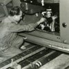
Making the wiring clusters:
Instalation of the the wiring harness:
First wired the ignition switch, B+ to light switch and idiot lights in odometer.
Today, I made the turn signal system using a 3 position lever and a 2 prong flasher. At first, there was not any light blinking because I mistakenly ran B+ from switch to the light in the odometer and then to the flasher. The right thing was: B+ to the bulb core (there is a connector above in the odometer frame) and the contact at the center of the bulb goes to the flasher.
The DC has the front turn signals working =D
video:
https://www.dropbox.com/s/uekk16vhku0qhio/2015-08-30%2022.55.35.mp4?dl=0
The plan for tomorrow is to connect the head lights, tail lights and brake indicator lights.
My DC project: http://www.thesamba.com/vw/forum/viewtopic.php?t=563792&highlight=
Regards ! |
|
BarryL 
Samba Member

Joined: November 01, 2004
Posts: 14269
Location: Casa de Oro, California
|
| Posted: Mon Aug 31, 2015 10:03 am Post subject: |
|
|
You gotta do what you got the means to do. Looks decent to me.
If you are using a the original or original style fuse junction array, be sure to clean it real well and try to solder the laminated sandwiches together as best you can. Eric & Barb have a technical article somewhere about how to do it. Basically you are guaranteeing that all the power getting sent through the connectors and fuse junctions isn't lessened. After all your hard work it would be bad to have the fuse block be a glitch. |
|
Alexmobil
Samba Member
Joined: November 28, 2010
Posts: 71
Location: El Salvador
|
| Posted: Mon Aug 31, 2015 3:17 pm Post subject: |
|
|
Thanks Barryl, I cleaned the fuse block but didnt solder. I will find the Eric & Barb article and follow his advice.
By the way, the wire size is the same as the wiring diagram, the only exception is the AWG 16 replacing the AWG20 because I didn´t find that size of wire. |
|