| Author |
Message |
Tumbledown76
Samba Member
Joined: June 16, 2015
Posts: 91
Location: Bussachusetts

|
 Posted: Tue Jul 04, 2017 4:39 pm Post subject: Auxiliary Battery Setup (Blue Sea Systems Setup) Posted: Tue Jul 04, 2017 4:39 pm Post subject: Auxiliary Battery Setup (Blue Sea Systems Setup) |
 |
|
Don't have much if any wiring xp. But I was inspired by Aeromech and Lintbrush's Add-A-Battery setup.
I used Lintbrush's exact parts list and wiring diagrams, but it still took a while to wrap my head around it all. Thanks again for all the help and back and forth, cheers to you.
Problem is on my setup, with the switch on OFF, the bus starts right up. And with the switch ON, it starts right up. And the radio does not turn on. Everything else seems fine. Hey, I'm still learning...but it seems I have bypassed the function of the Switch. Not sure where I have gone wrong.
On the old setup, The B+ red alternator wire used to connect to an isolator. The D+ wire was cut in half (the 16 awg red wire). The end which connects to the black plastic piece, which hooks into the Voltage Regulator, was then setup with a connector which hooked up to the isolator as well. The blue wire shares the same connection. The brown and green wire appear to be stock in the setup.
The general consensus, and my fault if I did not pm it clearly to a few folks, from some advise was it seemed I need to return the setup to Bentley stock setup. So I ran the B+ wire to the Starter post, and reconnected the D+ wire that was cut in half. Here are some images below with write-ups of the setup in the image description in the gallery.
_________________
'Camel' - '79 Riviera, 2.0L FI, Dakota Beige |
|
| Back to top |
|
 |
aeromech
Samba Member
Joined: January 24, 2006
Posts: 16954
Location: San Diego, California
|
| Posted: Tue Jul 04, 2017 5:56 pm Post subject: Re: Auxiliary Battery Setup (Blue Sea Systems Setup) |
|
|
Okay, let's try to work through this. In this picture I've circled a positive post with an unknown wire going off somewhere. I've also pointed an arrow at a fuse holder that has a wire going in but not coming out. Usually the missing wire should run north to an aux fuse panel up front. That fuse panel should power things like dome lights and stereo off the aux battery, saving the start battery to get home on.
Since you've used all the same color for your cables it's difficult to see where everything goes. Can you draw it out and share it here?
_________________
Lead Mechanic: San Diego Air and Space Museum
Licensed Airframe and Powerplant Mechanic
Licensed Pilot (Single engine Land)
Boeing 727,737-200-300-400,757,767
Airbus A319,320,321
DC9/MD80
BAe146
Fokker F28/F100
VW type 1 1962,63,65,69,72
VW Type 2 1971 (3 ea.) 1978, 1969
VW Jetta
VW Passat
Capable of leaping tall buildings in a single bound |
|
| Back to top |
|
|
aeromech
Samba Member
Joined: January 24, 2006
Posts: 16954
Location: San Diego, California
|
| Posted: Tue Jul 04, 2017 5:59 pm Post subject: Re: Auxiliary Battery Setup (Blue Sea Systems Setup) |
|
|
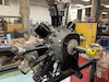
Also, you show a picture of the coil and you have a big red wire going to it. This is not something I've ever done with aux battery installations. Why the coil pic?
Edit: Oh I see now. It powers the relay that removes the ground from the ACR to prevent parasitic drain
_________________
Lead Mechanic: San Diego Air and Space Museum
Licensed Airframe and Powerplant Mechanic
Licensed Pilot (Single engine Land)
Boeing 727,737-200-300-400,757,767
Airbus A319,320,321
DC9/MD80
BAe146
Fokker F28/F100
VW type 1 1962,63,65,69,72
VW Type 2 1971 (3 ea.) 1978, 1969
VW Jetta
VW Passat
Capable of leaping tall buildings in a single bound
Last edited by aeromech on Tue Jul 04, 2017 6:01 pm; edited 1 time in total |
|
| Back to top |
|
|
Abscate
Samba Member
Joined: October 05, 2014
Posts: 22639
Location: NYC/Upstate/ROW
|
| Posted: Tue Jul 04, 2017 6:00 pm Post subject: Re: Auxiliary Battery Setup (Blue Sea Systems Setup) |
|
|
This really isn't something to be learning over the Internet. Pm me where you are in the Bay State  and I'll stop by on my next rounds and I'll stop by on my next rounds
_________________
.ssS! |
|
| Back to top |
|
|
aeromech
Samba Member
Joined: January 24, 2006
Posts: 16954
Location: San Diego, California
|
| Posted: Tue Jul 04, 2017 6:14 pm Post subject: Re: Auxiliary Battery Setup (Blue Sea Systems Setup) |
|
|
Okay, you might have some wires mixed up on the switch
Off hand I'd say you have the aux battery + going to the wrong terminal and the aux fuse panel wire too. I think you need to swap them.
_________________
Lead Mechanic: San Diego Air and Space Museum
Licensed Airframe and Powerplant Mechanic
Licensed Pilot (Single engine Land)
Boeing 727,737-200-300-400,757,767
Airbus A319,320,321
DC9/MD80
BAe146
Fokker F28/F100
VW type 1 1962,63,65,69,72
VW Type 2 1971 (3 ea.) 1978, 1969
VW Jetta
VW Passat
Capable of leaping tall buildings in a single bound |
|
| Back to top |
|
|
Tumbledown76
Samba Member
Joined: June 16, 2015
Posts: 91
Location: Bussachusetts
|
| Posted: Tue Jul 04, 2017 6:35 pm Post subject: Re: Auxiliary Battery Setup (Blue Sea Systems Setup) |
|
|
| aeromech wrote: |
Okay, you might have some wires mixed up on the switch
Off hand I'd say you have the aux battery + going to the wrong terminal and the aux fuse panel wire too. I think you need to swap them.
|
I followed this: https://www.google.com/search?q=add+a+battery+pack...hQEFQ8xKM:
And this:
https://www.thesamba.com/vw/forum/album_page.php?pic_id=1482593
Here are the picture descriptions I typed up when I uploaded the photos, with a few minor edits:
"Auxiliary/Left Side, I have yet to hook up the 6 awg wire in the 40 amp fuse blocker which will connect to a fuse panel under under the front dash. The black sheethed wire hooks up to the negative terminal and the red sheethed wire hooks up to the positive terminal are for an inverter that is mounted under the passenger bench. The 16 red awg wire in the foreground goes to the coil and comes from a Bosch relay, which prevents the battery from draining if the bus ends up sitting too long."
"B Terminal of the ACR runs to the 100 amp fuse blocker mounted on the auxiliary/left-side of the setup (see previous image). The ACR "A Terminal" runs into the this shown 100 amp fuse blocker. There are 3, 2 awg red wires going into the positive side of the 34R Optima positive terminal. One goes to the Starter, another to the switch on the right side of the setup as shown here, and the last connected to the other end of the 100 amp fuse blocker shown here. The 4 pin-Bosch relay setup prevents the battery from draining if the bus sits too long. This includes 2 16awg grounding wires, 1 16awg wire which connects to the coil using a piggyback connector, since my coil is full on the positive side. And the last 16awg wire to the ACR unit shownhere , as its ground connection."
"Shown is the red wire and piggyback connection to the coil. Said red 16 awg wire connect to the left side of the battery setup and connects into a Bosch relay which is setup to prevent the battery from draining if left undriven."
_________________
'Camel' - '79 Riviera, 2.0L FI, Dakota Beige |
|
| Back to top |
|
|
Tumbledown76
Samba Member
Joined: June 16, 2015
Posts: 91
Location: Bussachusetts
|
| Posted: Tue Jul 04, 2017 6:44 pm Post subject: Re: Auxiliary Battery Setup (Blue Sea Systems Setup) |
|
|
**Being aware that there are discrepancies in the year. For ie. I have a different Voltage Regulator wiring setup than shown in this diagram. This is a setup for a 1970.
_________________
'Camel' - '79 Riviera, 2.0L FI, Dakota Beige |
|
| Back to top |
|
|
aeromech
Samba Member
Joined: January 24, 2006
Posts: 16954
Location: San Diego, California
|
| Posted: Tue Jul 04, 2017 6:49 pm Post subject: Re: Auxiliary Battery Setup (Blue Sea Systems Setup) |
|
|
Why are you bypassing the switched power for the aux fuse block when you ran power to the inverter? I hope you have a fuse somewhere?
_________________
Lead Mechanic: San Diego Air and Space Museum
Licensed Airframe and Powerplant Mechanic
Licensed Pilot (Single engine Land)
Boeing 727,737-200-300-400,757,767
Airbus A319,320,321
DC9/MD80
BAe146
Fokker F28/F100
VW type 1 1962,63,65,69,72
VW Type 2 1971 (3 ea.) 1978, 1969
VW Jetta
VW Passat
Capable of leaping tall buildings in a single bound |
|
| Back to top |
|
|
Tumbledown76
Samba Member
Joined: June 16, 2015
Posts: 91
Location: Bussachusetts
|
| Posted: Tue Jul 04, 2017 7:11 pm Post subject: Re: Auxiliary Battery Setup (Blue Sea Systems Setup) |
|
|
Btw, are you still in the belief that the aux battery+ and fuse panel connections on the switch should be swapped, given directions on the outer packaging of the add-a battery system?
| aeromech wrote: |
| Why are you bypassing the switched power for the aux fuse block when you ran power to the inverter? I hope you have a fuse somewhere? |
There are two replaceable fuses on the back of the Pure Sine Wave Inverter. Am I missing something else there? What is the better way?
Also, I have not run or turned on the bus other to realize it ran in the OFF Position. And then again to test the ON position. I am not running it till I figure this out.
_________________
'Camel' - '79 Riviera, 2.0L FI, Dakota Beige |
|
| Back to top |
|
|
aeromech
Samba Member
Joined: January 24, 2006
Posts: 16954
Location: San Diego, California
|
| Posted: Tue Jul 04, 2017 7:22 pm Post subject: Re: Auxiliary Battery Setup (Blue Sea Systems Setup) |
|
|
You should follow the directions I listed per the diagram. I would run the inverter through the switch so when you kill the switch, everything is dead. You should check the other switch connections per the diagram too since you're having problems.
_________________
Lead Mechanic: San Diego Air and Space Museum
Licensed Airframe and Powerplant Mechanic
Licensed Pilot (Single engine Land)
Boeing 727,737-200-300-400,757,767
Airbus A319,320,321
DC9/MD80
BAe146
Fokker F28/F100
VW type 1 1962,63,65,69,72
VW Type 2 1971 (3 ea.) 1978, 1969
VW Jetta
VW Passat
Capable of leaping tall buildings in a single bound |
|
| Back to top |
|
|
Tumbledown76
Samba Member
Joined: June 16, 2015
Posts: 91
Location: Bussachusetts
|
| Posted: Tue Jul 04, 2017 7:34 pm Post subject: Re: Auxiliary Battery Setup (Blue Sea Systems Setup) |
|
|
| aeromech wrote: |
| You should follow the directions I listed per the diagram. I would run the inverter through the switch so when you kill the switch, everything is dead. You should check the other switch connections per the diagram too since you're having problems. |
Ok, I see on the inverter. Makes total sense.
Well ok then, according to your diagram, it appears I need to flip the connections on the 1 side, and the connections on the 2 side.
I understand the packaging on the Blue Sea systems is for a boat, but how come the connections are flipped opposite yours on their image?
_________________
'Camel' - '79 Riviera, 2.0L FI, Dakota Beige |
|
| Back to top |
|
|
aeromech
Samba Member
Joined: January 24, 2006
Posts: 16954
Location: San Diego, California
|
| Posted: Tue Jul 04, 2017 8:04 pm Post subject: Re: Auxiliary Battery Setup (Blue Sea Systems Setup) |
|
|
It might be the view. My diagram is a view of the back of the switch
_________________
Lead Mechanic: San Diego Air and Space Museum
Licensed Airframe and Powerplant Mechanic
Licensed Pilot (Single engine Land)
Boeing 727,737-200-300-400,757,767
Airbus A319,320,321
DC9/MD80
BAe146
Fokker F28/F100
VW type 1 1962,63,65,69,72
VW Type 2 1971 (3 ea.) 1978, 1969
VW Jetta
VW Passat
Capable of leaping tall buildings in a single bound |
|
| Back to top |
|
|
telford dorr
Samba Member

Joined: March 11, 2009
Posts: 3551
Location: San Diego (Encinitas)
|
| Posted: Tue Jul 04, 2017 9:32 pm Post subject: Re: Auxiliary Battery Setup (Blue Sea Systems Setup) |
|
|
| Tumbledown76 wrote: |
| Problem is on my setup, with the switch on OFF, the bus starts right up. And with the switch ON, it starts right up. |
I see three heavy wires connecting to the battery "+" terminal. Your schematic shows only two. Because the starter is wired directly to the Start battery (instead of the switch), it will start regardless of the switch position. That starter wire needs to go to the switch, according to the instruction sheet.
| Quote: |
On the old setup, The B+ red alternator wire used to connect to an isolator. The D+ wire was cut in half (the 16 awg red wire). The end which connects to the black plastic piece, which hooks into the Voltage Regulator, was then setup with a connector which hooked up to the isolator as well. The blue wire shares the same connection. The brown and green wire appear to be stock in the setup.
The general consensus, and my fault if I did not pm it clearly to a few folks, from some advise was it seemed I need to return the setup to Bentley stock setup. So I ran the B+ wire to the Starter post, and reconnected the D+ wire that was cut in half. Here are some images below with write-ups of the setup in the image description in the gallery. |
I'd connect the B+ wire to the Start battery as shown in the instruction sheet, not to the starter, to guarantee that the alternator always has a battery load (which could otherwise disappear if the switch were set to 'all off' position). Restore the D+ connection to stock.
The only issue will be if you start from the house battery, the ALT light will be referenced to that, while the alternator will be referenced to the start battery. This may make the light glow, but its indication is only valid when the switch is set to the normal connection position.
_________________
'71 panel, now with FI
'Experience' is the ability to recognize a mistake when you're making it again - Franklin P. Jones
In theory, theory works in practice; in practice, it doesn't - William T. Harbaugh
When you're dead, you don't know you're dead. The pain is only felt by others.
Same thing happens when you're stupid. - Philippe Geluck
More VW electrical at http://telforddorr.com/ (available 9am to 9pm PST)
Last edited by telford dorr on Wed Jul 05, 2017 9:52 am; edited 1 time in total |
|
| Back to top |
|
|
Tumbledown76
Samba Member
Joined: June 16, 2015
Posts: 91
Location: Bussachusetts
|
| Posted: Wed Jul 05, 2017 8:08 am Post subject: Re: Auxiliary Battery Setup (Blue Sea Systems Setup) |
|
|
| aeromech wrote: |
| It might be the view. My diagram is a view of the back of the switch |
Right, and that is how my initial setup is. I was addressing flipping/swapping these with each other as shown on your drawn over image:
| telford dorr wrote: |
| I see three heavy wires connecting to the battery "+" terminal. Your schematic shows only two. Because the starter is wired directly to the Start battery (instead of the switch), it will start regardless of the switch position. That starter wire needs to go to the switch, according to the instruction sheet. |
I initially thought the same thing when I started this and contacted the creator of the diagram. I was told that the diagram only included the wires there were added. The one exception was the blue coded wire from the voltage regulator to the battery, as it was it was already there. But that indeed, I needed to have a wire going from the main starting battery to the starter too. So I went ahead and created a new 2awg red cable that ran from the starter to the battery, so it could daisy chain off the battery+ post with the other new cables. The military grade battery+ post lug apparently allows up to 4 connections maximum (not that I would go beyond that).
| telford dorr wrote: |
| I'd connect the B+ wire to the Start battery as shown in the instruction sheet, not to the starter, to guarantee that the alternator always has a battery load (which could otherwise disappear if the switch were set to 'all off' position). |
I've Gotten some conflicting advise on this one...certainly, not saying your suggestion is wrong. You guys clearly know more about this than I.
| telford dorr wrote: |
| Restore the D- connection to stock |
My D- wire, the green wire going into the plastic piece which connects to the VR, was always stock. Perhaps you meant the D+ which yes, I have returned to stock. 
| telford dorr wrote: |
| The only issue will be if you start from the house battery, the ALT light will be referenced to that, while the alternator will be referenced to the start battery. This may make the light glow, but its indication is only valid when the switch is set to the normal connection position. |
I take it that's not 'normal' behavior then? How does this get avoided.
Thanks everyone for helping on this. I greatly appreciate it.
Tumble
_________________
'Camel' - '79 Riviera, 2.0L FI, Dakota Beige |
|
| Back to top |
|
|
aeromech
Samba Member
Joined: January 24, 2006
Posts: 16954
Location: San Diego, California
|
| Posted: Wed Jul 05, 2017 9:32 am Post subject: Re: Auxiliary Battery Setup (Blue Sea Systems Setup) |
|
|
Telford is right. Remove the cable between the start battery + and the starter lug. It bypasses the switch. Also, Telford is always right about electrical so listen to what he says
_________________
Lead Mechanic: San Diego Air and Space Museum
Licensed Airframe and Powerplant Mechanic
Licensed Pilot (Single engine Land)
Boeing 727,737-200-300-400,757,767
Airbus A319,320,321
DC9/MD80
BAe146
Fokker F28/F100
VW type 1 1962,63,65,69,72
VW Type 2 1971 (3 ea.) 1978, 1969
VW Jetta
VW Passat
Capable of leaping tall buildings in a single bound |
|
| Back to top |
|
|
Tumbledown76
Samba Member
Joined: June 16, 2015
Posts: 91
Location: Bussachusetts
|
| Posted: Wed Jul 05, 2017 9:46 am Post subject: Re: Auxiliary Battery Setup (Blue Sea Systems Setup) |
|
|
| aeromech wrote: |
| Telford is right. Remove the cable between the start battery + and the starter lug. It bypasses the switch. Also, Telford is always right about electrical so listen to what he says |
Roger that.
Thanks aeromech
_________________
'Camel' - '79 Riviera, 2.0L FI, Dakota Beige |
|
| Back to top |
|
|
telford dorr
Samba Member
Joined: March 11, 2009
Posts: 3551
Location: San Diego (Encinitas)
|
| Posted: Wed Jul 05, 2017 9:47 am Post subject: Re: Auxiliary Battery Setup (Blue Sea Systems Setup) |
|
|
| Tumbledown76 wrote: |
| telford dorr wrote: |
| The only issue will be if you start from the house battery, the ALT light will be referenced to that, while the alternator will be referenced to the start battery. This may make the light glow, but its indication is only valid when the switch is set to the normal connection position. |
I take it that's not 'normal' behavior then? How does this get avoided. |
Actually, don't worry about this - it won't happen with the switch you've chosen. I looked it up, and if I'm right, it's an "off / on / combined" switch. It either disconnects or connects both batteries from/to their respective loads, or ties everything together. Thus, the situation I previously described can't happen. I was thinking of a conventional "boat" battery switch where the load can be connected to either battery, or to both, or disconnected (load = A, B, A + B, off). Sorry 'bout that...
Also, fixed the D+ error (above).
Not always right... (but trying)
_________________
'71 panel, now with FI
'Experience' is the ability to recognize a mistake when you're making it again - Franklin P. Jones
In theory, theory works in practice; in practice, it doesn't - William T. Harbaugh
When you're dead, you don't know you're dead. The pain is only felt by others.
Same thing happens when you're stupid. - Philippe Geluck
More VW electrical at http://telforddorr.com/ (available 9am to 9pm PST) |
|
| Back to top |
|
|
Abscate
Samba Member
Joined: October 05, 2014
Posts: 22639
Location: NYC/Upstate/ROW
|
| Posted: Wed Jul 05, 2017 10:32 am Post subject: Re: Auxiliary Battery Setup (Blue Sea Systems Setup) |
|
|
I think most people would be much better served with the
Battery A
Battery B
Battery A+B
Off
type switch, then matching batteries in type/age
Daily driving, alternate batteries each week (on boats we use odd battery on odd days, even battery on even days)
Remember to not switch between batteries with engine running if you have an alternator without turning engine off.
_________________
.ssS! |
|
| Back to top |
|
|
aeromech
Samba Member
Joined: January 24, 2006
Posts: 16954
Location: San Diego, California
|
| Posted: Wed Jul 05, 2017 10:39 am Post subject: Re: Auxiliary Battery Setup (Blue Sea Systems Setup) |
|
|
The ACR automatically combines the batteries for charging eliminating having to touch the switch. It's a great system
_________________
Lead Mechanic: San Diego Air and Space Museum
Licensed Airframe and Powerplant Mechanic
Licensed Pilot (Single engine Land)
Boeing 727,737-200-300-400,757,767
Airbus A319,320,321
DC9/MD80
BAe146
Fokker F28/F100
VW type 1 1962,63,65,69,72
VW Type 2 1971 (3 ea.) 1978, 1969
VW Jetta
VW Passat
Capable of leaping tall buildings in a single bound |
|
| Back to top |
|
|
Tumbledown76
Samba Member
Joined: June 16, 2015
Posts: 91
Location: Bussachusetts
|
| Posted: Wed Jul 05, 2017 11:59 am Post subject: Re: Auxiliary Battery Setup (Blue Sea Systems Setup) |
|
|
| aeromech wrote: |
| You should follow the directions I listed per the diagram. I would run the inverter through the switch so when you kill the switch, everything is dead. You should check the other switch connections per the diagram too since you're having problems. |
So where exactly on the switch to you advise putting the Inverter+ cable? On your diagram would it now go to the upper left connection (sharing the aux bat+ post on the side labeled "1"). Can the inverter ground wire share the same large ground bolt that the aux battery ground shares?
Cheers!
_________________
'Camel' - '79 Riviera, 2.0L FI, Dakota Beige |
|
| Back to top |
|
|
|


