| Author |
Message |
aeromech
Samba Member
Joined: January 24, 2006
Posts: 16961
Location: San Diego, California

|
 Posted: Mon Apr 20, 2009 12:43 pm Post subject: Posted: Mon Apr 20, 2009 12:43 pm Post subject: |
 |
|
| Jody '71 wrote: |
Aero,
I can see why you don't see the need for the diode, having a 20 year old VDO tach that probably didn't need one, nor a current production model that needs one either. There was a production run of the VDO tachs years back that were sh*t outta the box with improper instructions. Many found that the diode was the only fix. |
Really, I'm surprised that a company like VDO would have such poor quality assurance. |
|
| Back to top |
|
 |
exvwmd
Samba Member

Joined: February 27, 2006
Posts: 156
|
| Posted: Mon Apr 20, 2009 1:24 pm Post subject: VDO tach |
|
|
I have had ALL the same problems with my VDO tach. It NEVER was accurate,not even close from the very begining.{off by as much as 1000rpm's too low} Called the main office where I bought it and they told me to set it to the 6 cyld setting. Can you imagine that? I did it and now it is ONLY off by about 400 rpm's higher at 65 mph. Great huh? I am done with ALL vdo gauges {pressure and temp gauges are off too.} Any one know a better brand for VW gauges? 
_________________
Mary Jane Muggles Lives! |
|
| Back to top |
|
|
telford dorr
Samba Member

Joined: March 11, 2009
Posts: 3551
Location: San Diego (Encinitas)
|
| Posted: Mon Apr 20, 2009 1:28 pm Post subject: |
|
|
| aeromech wrote: |
For the life of me I can't understand the need for the diode. Like I said, I ran a VDO tach in my bus for well over 20 years with zero issues or problems. If it's not broken, why fix it? My stereo cranked out the tunes Dude. |
Well, the reason I want it (regardless of what the VDO tach needs) has to do with the way ignition systems work: when the points open, along with a really high voltage being sent to the spark plug, you get a proportionally high voltage on the primary side of the coil (as a function of the coil's turns ratio.) This positive pulse can be many hundreds of volts high. This is the primary signal you see on an ignition scope which shows the dwell angle.
Now, because a diode conducts in only one direction, it blocks that positive pulse from being sent to the tach. but does allow the closing of the points to be seen by the tach. (That's why you use a 1N4007 - it's rated at 1 kv.) The resistor and capacitor further slow down the rapid rise time on this waveform, reducing it to a (relative) low voltage waveform which matches the points opening and closing. This is all that the tach should need.
Without this filter network, you have 15 ft of wire from the coil to the front of the bus radiating ignition noise into everything electronic in the bus. This gives you a background buzz in your radios and stereo. This I do not need or want.
With electronic (point-less) ignition, the risetime of this noise waveform is many times worse.
Now if I were VDO, I'd have included a small module with the tach package which mounts right next to the coil and does this signal conditioning. But that costs more...
[In piston aircraft, they circumvent this problem by running the primary mag leads in shielded cable, from the mag to the mag switch. Keeps the com and nav receivers happy...]
TD |
|
| Back to top |
|
|
aeromech
Samba Member
Joined: January 24, 2006
Posts: 16961
Location: San Diego, California
|
| Posted: Mon Apr 20, 2009 1:56 pm Post subject: |
|
|
| I don't dispute anything you said Telford. Obviously you have a lot of knowledge here. The only thing I'm saying is that I've install two of the VDO's into buses and never had any issues with accuracy or noise and I never did anything in the electrical system to counter that. In one bus I actually did have electronic ignition running too. |
|
| Back to top |
|
|
Air_Cooled_Nut
Samba Member

Joined: March 27, 2004
Posts: 3040
Location: Portland, Oregon
|
| Posted: Mon Apr 20, 2009 3:09 pm Post subject: |
|
|
| telford dorr wrote: |
Well, the reason I want it (regardless of what the VDO tach needs) has to do with the way ignition systems work...blah blah yadda-yadda |
It's a 30+ year old VW BUS, not an aircraft, so there's no need to go psycho on keeping everything EMI-proof 
_________________
Toby http://www.aircoolednut.com/
Did I mention that I'm an original Darksider?
'72 VW Squareback, 2007cc, GB 5-speed, rag top; '76 VW Riviera Penthouse Sundowner 2.0L; 2015 Audi S5 Cabby w/Stage II APR; '06 Ducati Sport Classic 1000; '14 Ducati Diavel Strada
The First Invasion |
|
| Back to top |
|
|
telford dorr
Samba Member
Joined: March 11, 2009
Posts: 3551
Location: San Diego (Encinitas)
|
| Posted: Mon Apr 20, 2009 3:30 pm Post subject: |
|
|
| Air_Cooled_Nut wrote: |
It's a 30+ year old VW BUS, not an aircraft, so there's no need to go psycho on keeping everything EMI-proof |
I just get tired of a (faint) whine in the radio that varies with engine speed.... If it doesn't bother you, or if you don't have that problem, then don't sweat it. To each his own. |
|
| Back to top |
|
|
telford dorr
Samba Member
Joined: March 11, 2009
Posts: 3551
Location: San Diego (Encinitas)
|
| Posted: Mon Apr 20, 2009 4:18 pm Post subject: |
|
|
| aeromech wrote: |
| I don't dispute anything you said Telford. Obviously you have a lot of knowledge here. The only thing I'm saying is that I've install two of the VDO's into buses and never had any issues with accuracy or noise and I never did anything in the electrical system to counter that. In one bus I actually did have electronic ignition running too. |
To be clear, a properly designed tach (VDO or otherwise) should indicate correctly without the user having to modify the installation by adding components, so your experience should be the norm.
My concern is with ignition noise getting into other electronics, and it sounded like someone has worked out a signal filter network that I would prefer to use as a starting point and that might solve this problem. I have not installed this tach myself, but I have installed a trip computer on this bus and have noticed noise from the ignition wire from the points. [Note: this signal was not ultimately needed for the trip computer and the wire was subsequently removed, which solved the immediate noise problem.]
On the other hand, it sounds to me, judging from other comments, that some people are having issues with this tach, so it would imply either a weakness in its design or a sensitivity to proper installation (including wire length, dress, supply voltage, proper grounding, etc.) that people are compensating for by adding the diode. When I do get around to buying and putting in the tach, I fully intend to open it, if it can be done without bending / breaking it, experiment with it, and reverse engineer it. Most of these circuits are fairly straight forward, so if I see anything glaring that could cause the symptoms described by others, I'll report it here.
As an aside, in my general experience, most automotive gauge problems are related to grounding of sensors or indicators such that the grounds of the two are actually at the same potential! Bad engine to frame ground straps, choice of ground points, etc., etc. are problematic at best. Second on the list is a flaky choice of 12 volt power source. Third is wiring methods (specifically crimp terminals [or a lack thereof] and their installation method.)
A (distant) fourth is poor gauge design.
FWIW
TD
|
|
| Back to top |
|
|
Traveling Writer
Samba Scribe

Joined: May 07, 2006
Posts: 1112
Location: Florence, Italy
|
| Posted: Wed Apr 22, 2009 8:35 am Post subject: Dip Switch Settings on a VDO Tach--CORRECT SETTINGS |
|
|
The VDO instructions/PDF is WRONG.
The correct settings are: 123; UP DOWN DOWN
I had it set according to the instructions, the needle got to 500 rpms at good revving. Reset the switches (vdo in place) with a tiny mirror and screwdriver. Works like a charm. Needle is steady as a rock with the diode in place. I used a diode that ends in 07, not 05.
And how do you edit the title of your post?? I'd like to add that the problem is solved for future searches...Everett?
_________________
Cheers,
Davi
1977 2.0 FI Westy
2011 1200cc Yamaha Super Tenere
1976 Feet (they work surprisingly well) |
|
| Back to top |
|
|
Air_Cooled_Nut
Samba Member
Joined: March 27, 2004
Posts: 3040
Location: Portland, Oregon
|
| Posted: Wed Apr 22, 2009 8:42 am Post subject: Re: Dip Switch Settings on a VDO Tach--CORRECT SETTINGS |
|
|
| Traveling Writer wrote: |
...
And how do you edit the title of your post?? I'd like to add that the problem is solved for future searches...Everett? |
I'd like to know that as well.
_________________
Toby http://www.aircoolednut.com/
Did I mention that I'm an original Darksider?
'72 VW Squareback, 2007cc, GB 5-speed, rag top; '76 VW Riviera Penthouse Sundowner 2.0L; 2015 Audi S5 Cabby w/Stage II APR; '06 Ducati Sport Classic 1000; '14 Ducati Diavel Strada
The First Invasion |
|
| Back to top |
|
|
ScottK
Samba Member

Joined: August 28, 2004
Posts: 1748
Location: Avilla America
|
| Posted: Wed Apr 22, 2009 3:16 pm Post subject: Re: Dip Switch Settings on a VDO Tach--CORRECT SETTINGS |
|
|
| Air_Cooled_Nut wrote: |
| Traveling Writer wrote: |
...
And how do you edit the title of your post?? I'd like to add that the problem is solved for future searches...Everett? |
I'd like to know that as well. |
Just hit edit on your first post in the thread. You can edit the title there. |
|
| Back to top |
|
|
aeromech
Samba Member
Joined: January 24, 2006
Posts: 16961
Location: San Diego, California
|
| Posted: Wed Apr 22, 2009 6:37 pm Post subject: |
|
|
Here's some new information and I may need to eat some crow.
I have an engine test stand and a control box with a VDO tach as well as oil pressure and voltage gauges. It's got a low oil pressure idiot light, a green light to show that ignition is active and a starter switch. I haven't used this very much... it's pretty new.
Today I test ran a type 3 engine and the tach was erratic. I was thinking in the past that this was probably caused by the control box being too close to the coil and that I needed shielded cable but after today's discussion I'm wondering if I need the diode previously mentioned. What do you guys think?
|
|
| Back to top |
|
|
SteveStevieStevens
Samba Member

Joined: November 09, 2006
Posts: 105
Location: Boise, ID
|
| Posted: Thu Apr 23, 2009 5:31 pm Post subject: |
|
|
Don't some of the newer alternators fix the radio whine issue with a diode on the back of the alternator? I know the one I recently bought did.
That might be the difference between those who had the needle jump and those who didn't.
I'm far from an expert though. |
|
| Back to top |
|
|
Air_Cooled_Nut
Samba Member
Joined: March 27, 2004
Posts: 3040
Location: Portland, Oregon
|
| Posted: Thu Apr 23, 2009 6:26 pm Post subject: |
|
|
| aeromech wrote: |
...
Today I test ran a type 3 engine and the tach was erratic. I was thinking in the past that this was probably caused by the control box being too close to the coil and that I needed shielded cable but after today's discussion I'm wondering if I need the diode previously mentioned. What do you guys think?... |
I own a T3 with [my custom] alternator and previously with a [stock] generator, using the same tach that you have in your Bus. Never, ever, a bouncy needle.
_________________
Toby http://www.aircoolednut.com/
Did I mention that I'm an original Darksider?
'72 VW Squareback, 2007cc, GB 5-speed, rag top; '76 VW Riviera Penthouse Sundowner 2.0L; 2015 Audi S5 Cabby w/Stage II APR; '06 Ducati Sport Classic 1000; '14 Ducati Diavel Strada
The First Invasion |
|
| Back to top |
|
|
aeromech
Samba Member
Joined: January 24, 2006
Posts: 16961
Location: San Diego, California
|
| Posted: Thu Apr 23, 2009 7:38 pm Post subject: |
|
|
| Air_Cooled_Nut wrote: |
| aeromech wrote: |
...
Today I test ran a type 3 engine and the tach was erratic. I was thinking in the past that this was probably caused by the control box being too close to the coil and that I needed shielded cable but after today's discussion I'm wondering if I need the diode previously mentioned. What do you guys think?... |
I own a T3 with [my custom] alternator and previously with a [stock] generator, using the same tach that you have in your Bus. Never, ever, a bouncy needle. |
Yes, but was it three feet from the coil? |
|
| Back to top |
|
|
Air_Cooled_Nut
Samba Member
Joined: March 27, 2004
Posts: 3040
Location: Portland, Oregon
|
| Posted: Thu Apr 23, 2009 8:20 pm Post subject: |
|
|
No, it's mounted in the stock clock location, up in the dash, as any good gauge should be 
_________________
Toby http://www.aircoolednut.com/
Did I mention that I'm an original Darksider?
'72 VW Squareback, 2007cc, GB 5-speed, rag top; '76 VW Riviera Penthouse Sundowner 2.0L; 2015 Audi S5 Cabby w/Stage II APR; '06 Ducati Sport Classic 1000; '14 Ducati Diavel Strada
The First Invasion |
|
| Back to top |
|
|
aeromech
Samba Member
Joined: January 24, 2006
Posts: 16961
Location: San Diego, California
|
| Posted: Thu Apr 23, 2009 8:31 pm Post subject: |
|
|
| Air_Cooled_Nut wrote: |
| No, it's mounted in the stock clock location, up in the dash, as any good gauge should be |
That is unless you are using it in a test stand like my situation. |
|
| Back to top |
|
|
telford dorr
Samba Member
Joined: March 11, 2009
Posts: 3551
Location: San Diego (Encinitas)
|
| Posted: Sun May 17, 2009 8:07 pm Post subject: |
|
|
VDO Tachometer Fix
OK, got a VDO tach (333051D) for my 71 bus. Wanting to avoid post installation hassles with this thing, I did a bench test on the unit. Set the switches, hooked it up to a 12 volt power supply, and applied a 12 volt square wave from a Tektronix 114 pulse generator. When the frequency of the generator was 133.3 hz, the tach indicated 4000 rev / min. Wohoo! It works, and the calibration is right! Also checked at 2000 and 6000 rev / min. Both were close enough.
"OK, self, this should be a piece of cake install," I say. Little did I know...
So install the unit in the dash, wire up to ground (at the dash junction) and +12 volts (at the idiot light supply junction.) Run a length of #16 wire back the the engine bay, dressing it in with the air cond harness, tie-wrapping it up securely.
Of course, there's always side projects: welded up the sheet metal screw holes for the front cover pan, re-drilled, painted bare metal and re-installed the screws so the pan was nice and tight again.
So, time for a test drive. Start it up. Stupid tach is jumping all over hell. Spin the engine up a little, and the tach pegs at 7K. Damn!
So check everything: power and ground measure out at 14.2 volts, with the engine running, so that's OK. Put a 'scope on the points signal line: looks OK.
Fig 1 - Raw points Waveform
[Note: the labeling for the vertical axis in the waveform above is incorrect - it's actually 50 volts / division.]
As you can see, the points voltage spikes to 230 volts positive to 80 volts negative, with quite a bit of oscillation. This is a normal waveform.
Installing a 1N4005 diode in the signal line, per the VDO tech note, didn't fix it.
So, what's with the tach? POS! My only conclusion is that their circuit design is marginal to poor, and can't handle the real world. On the other hand, since it looks good in the dash, and works well on the bench, maybe we can fix this. So I set about to create my own "front end" buffer circuit.
Fig 2 - Prototype board
Fig 3 - Prototype close-up
Fig 4 - Schematic
As you can see, the circuit is a simple circuit, based on the ubiquitous, good for almost anything LM555 timer chip. In this case, we're using it strictly as a Schmitt-trigger inverting buffer. The real work is done in the preceding input signal conditioning circuitry. The prototype was built on a chunk of perf board and cobbed up to the engine so measurements could be made. I'll post pics of the final packaging when it gets done.
The following Circuit Description is for those interested in exactly how the circuit works, so that you can modify or adapt it to your needs.
The raw points signal enters through resistor R1. R1 has a high enough value such that there is virtually no loading on the points signal. R1 and capacitor C1 form a low-pass filter which removes most of the ringing from the waveform. Diodes D1 and D2 clamp the signal to between 0 and 12 volts.
Fig 5 - After one level of filtering
As you can see, most of the nastiness has been removed from the waveform, but not all. We can do better.
R2 and C2 form a second low-pass filter, removing all remaining ringing from the waveform.
Fig 6 - After two levels of filtering
So now we have a nice clean waveform, but the signal impedance is way too high to connect to the tach, so the LM555 chip buffers the signal. This chip can supply about 200 ma of drive, so you should be able to easily drive the tach. Also, this chip can take up to 18 volts of supply voltage, so it should easily survive in an automotive electrical environment. Just in case, resistor R4 was added to act as a fuse, and to smooth out the input power a little. C3, C4, and C5 remove any input power noise. The chip inverts the signal polarity, but the tachometer doesn't care.
Fig 7 - Final output to the tach
Just for fun, R3 and the LED form a built-in static timing light, in case you have to statically time the engine in the field.
Parts for this circuit used to be available at Radio Shack, but they seem to want not to be in this business any more. It should be easy to find parts on-line (in the USA, Mouser Electronics, if nowhere else.)
This pic shows the prototype board cobbed into the engine bay for development.
Fig 8 - Prototype in engine bay
Fig 9 - Closeup of prototype in engine bay
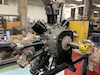
This pic shows why the board was cobbed in where it was - too hard to get probes to the coil...
Fig 10 - Hidden ignition coil
Fig 11 - Circuit under development
Since adding this buffer circuit, the tach display is completely stable and smooth, without a hint of jumpiness.
Side note: the lamps in the tach were way too bright at night, compared to the other dash instruments. This was solved by adding around 18 ohms in series with the feed wire to the lights. You can use an 18 ohm 2 watt resistor. I used four 4.3 ohm, 1/2 watt resistors in series (because I had them in stock), covered with a length of heat shrink tubing.
So, you may ask, this seems a little complex for what it does. For me, it solves several problems: (a) makes the tach work flawlessly, (b) avoids running a multi-hundred volt points signal all over the bus, incurring electrical noise in the audio equipment, and (c) isolates the signal line from the points so that any failure or loading in wiring downstream won't affect engine operation. In the future, I plan on adding a circuit to drop power to the AC compressor above a preset speed, so that you can go fast when needed without worrying about the compressor over-speeding and blowing up.
Note: I did not open the tach to reverse engineer it's innards and find out why it works so poorly out of the box, as it's a new tach and that would have involved mangling / removing the outer trim ring. If anybody has an old tach that they would be willing to donate to the cause (non-working is fine), I'll open it, document it's innards, and post the results here. I'm sure it's modifiable internally, so it will work right on a Bay without an external circuit. If the tach isn't working, I'll try to fix it, free, assuming parts are available, and return it to you. Email me if interested.
Last edited by telford dorr on Thu May 21, 2009 11:17 am; edited 2 times in total |
|
| Back to top |
|
|
aeromech
Samba Member
Joined: January 24, 2006
Posts: 16961
Location: San Diego, California
|
| Posted: Sun May 17, 2009 10:29 pm Post subject: |
|
|
| Do they give Nobel prizes for VW bus engineering? |
|
| Back to top |
|
|
kjspgd
Samba Member

Joined: June 13, 2008
Posts: 52
Location: Fairport, NY
|
| Posted: Thu May 28, 2009 8:27 am Post subject: |
|
|
Telford-
This is a cool and timely bit of information.
I've got an old harley 2stroke tach mounted (don't ask. PPO... but it's grown on me) and I've been prototyping an inline flip-flop get the tach to only receive every other pulse. I saw some weird results (not quite divide by 2) and thought it might have been related to sloppy signal. I'll try the low-pass filter and move up to the full on buffer if needed. |
|
| Back to top |
|
|
telford dorr
Samba Member
Joined: March 11, 2009
Posts: 3551
Location: San Diego (Encinitas)
|
| Posted: Thu May 28, 2009 11:27 am Post subject: |
|
|
Should work fine. Instead of the 555, you can go to 4000 series cmos logic - a Schmitt hex inverter and a flip-flop; buffer the ff output with paralleled leftover inverters. Let me know how it works out.
_________________
'71 panel, now with FI
'Experience' is the ability to recognize a mistake when you're making it again - Franklin P. Jones
In theory, theory works in practice; in practice, it doesn't - William T. Harbaugh
When you're dead, you don't know you're dead. The pain is only felt by others.
Same thing happens when you're stupid. - Philippe Geluck
More VW electrical at http://telforddorr.com/ (available 9am to 9pm PST) |
|
| Back to top |
|
|
|


