| Author |
Message |
nlorntson
Crazy VW Lady

Joined: March 13, 2004
Posts: 3783
Location: Twin Cities, MN

|
 Posted: Fri Feb 03, 2012 9:38 am Post subject: Split case transmission rebuild DIY Posted: Fri Feb 03, 2012 9:38 am Post subject: Split case transmission rebuild DIY |
 |
|
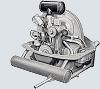
I looked throughout theSamba for a DIY transmission rebuild and found only advice on good rebuilders. So, in keeping with my 1955 budget build, and having a 52-57 Bentley manual, I decided to have a go at it myself. I though I would share what I did so others might find it useful.
The split case, partial syncro is an amazingly simple design and actually seems pretty hard to screw up. The Bentley manual has great instructions and plenty of pictures I think the biggest challenge is probably to get every thing cleaned.
I started by pulling off the axle tubes and mounting the left half of the tranny on my engine stand. I pulled both drain plugs and all three adjustment covers and let it sit draining overnight. There were two gaskets per side on the covers.
Next I pulled off the nosecone carefully so I could see the preload gaskets and how they were installed. Everything was so full of gear lube that it came apart pretty easily. I used a brand new utility knife blade to scrape under the gasket and lift it off.
Next I removed all the case bolts and rotated the transmission with the left side down.
I used a rubber mallet on the tabs along the seam, and inside the bell housing to get the case to begin to split apart. Once I had a gap started, I used a couple of nylon wedges to help the separation. The case is soft aluminum so don't use a metal prying tool or you'll damage the mating surfaces.
The right case half came off with the bearing which was good. Next I lifted out the main shaft and the pinion shaft. Finally I rotated the case half over and screwed an axle nut on the left axle to prevent the threads from being damaged. With very minimal effort, a couple of hits with a brass headed mallet on the axle nut and the whole final drive with both axles came out of the other case half.
Despite having drained for a couple of days, there was still a lot of gear oil inside so I put a big Rubbermaid container under to catch the drips. This also caught the reverse gear shaft pin and the bearing shim that both fell off when I rotated the case over to drive out the differential (Final drive aka crown gear). Yikes! I had better pay closer attention.
The left half is where the shifting forks are. I used an 11mm socket to loosen the three shifter fork bolts. These hold the forks on the rods. These have to come out to get the shifter forks out.
I knew there was a ball bearing and spring hiding somewhere under each of the shift fork rods so I laid a rag over the rod as I pulled each out. Good thing because that ball bearing popped right out once the rod had cleared. Once the 1st/2nd and the 3rd/4th rods and forks were out, I drove out the pin for the reverse gears and the gears and fork came out. Another part to watch for are the two shift rod locks. These are easy to lose.
I used a big tub of lacquer thinner to soak all the small parts. I used another large Rubbermaid tub and scrubbed the inside and outside with the thinner to get the inch of gunk out of the case halves. More cleaning with lacquer thinner and I ran both case halves through the glass bead blaster. There was some aluminum corrosion on the bottom near the drain holes so I hit that area hard to get all the crust out.
After the glass bead cleaning I scrubbed the halves inside and out with hot, soapy water and a rinse with super hot water. I did this a couple of times to ensure the case was clean inside and out.
For the rest of the internal guts, I soaked and scrubbed with a variety of tooth brushes, nylon brushes, brass brushes, etc in the lacquer thinner until it ran clear.
I did a close inspection of the pinion shaft, gears, syncros snap rings, bearings, etc. and other than a small amount of wear on the first gear teeth, the rest was in what appeared to be excellent shape so I opted to not disassemble the pinion shaft or the main shaft. I did pull off the first gear to inspect it and the syncros, shift plates, and springs.
Getting first gear back on requires a long fingers to hold all three shift plates on the gear until the gear can hold them in place. Be sure to line up the syncro so the gear can go all the way on.
The main shaft was also in good shape so I covered up everything from the seal surface to the end and gave the input shaft a good cleaning I the bead blast cabinet. That was also soaked and scrubbed and hot rinsed to remove all rust and crud.
With all the parts and the case halves nice and clean, I began to reassemble. First I installed the bearing into the case halves. I supported the opening and gently tapped the bearing into the opening using a brass headed hammer. Once it was in halfway I used a pair of 40 sump covers (they have a hole in the center) and a bolt and nut to press it into position. I did this on the other side as well.
Next was the reverse fork, gear and shaft. I used a little gear lube on the pin. There are differences in the reverse gear shaft and gears over the 1952-57 period so be sure to get any oil passages in early ones lined up properly. I made the mistake to install the gear and shaft first and then the shaft but that meant the shifter could not be in the proper spot. I corrected it later by removing the lock pin, shaft and gear and repositioning it.
The shifter, shaft and gears need to go in together. Don't forget to install the little pin that holds the shaft in place. Once th shaft is lined up, it just drops in. I gently tapped on the shaft to lock it in place, and I put a piece of tape to temporarily keep it in place. Adjust the fork on the shaft so when the rod is fully out or fully in, the gears are not too far in either direction. You can check this by temporarily positioning the main shaft in place and then shifting in and out of reverse. Tighten the bolt to18 ftlbs.
Next came the 1st/2nd Shaft. Don't forget to install the oblong detent lockout that sits between the reverse and 1st/2nd shafts before you slide the shaft in place. This functions to allow only one of the two side by side shafts from moving in or out at a given time.
Put the shaft in the hole and thread on the shift fork. Pay attention to the location of the adjusting hole to know which direction the fork slides on the rod. Screw the bolt in finder tight.
You'll need to press the ball down as you push the rod into the opening. I used an thin screw driver from the opposite side to lever the ball down as I pushed the end of the rod in. You'll hear a click if the ball is properly engaging with the shift rod. Put the second detent in before you slide the 3rd/4th shaft in. The 3rd/4th goes in the same way. Check to see that all shafts move in and out with a satisfying click.
(In this picture, I have the reverse shifter installed WRONG. The fork should sit between the two gears. I corrected my mistake by pulling the shaft pin and driving the shaft back out)
Now you can drop the pinion shaft and in and get the forks adjusted. Tap the nut in the end so the snap ring is seated against the case. Start with the 1st/2nd one. Adjust it so the first gear is fully engaged when the rod is all the way in and the gear is fully engaged to second when the rod is fully out. Once you have the fork positioned, tighten the 11mm bolt to 18ftlbs. Adjust 3rd/4th the same way. Keep checking to see that the pinion shaft remains properly seated. Put the main shaft in and rotate it as you shift through the gears. Be sure that they all operate smoothly.
Once both forks are positioned and tightened, put some sealant (I used permatex aviation) on the adjustment covers and use a 19mm box wrench to tighten then into the case.
Next take the pinion and main shaft out to put the final drive back in. I did not disassemble this either as it was in good shape and still had the factory assembly wire holding it all together. I put the spacer over the axle and onto the drive. I held it in place as I lowered the axle shaft through the case. Again I used a brass headed mallet and tapped on the face of the crown gear to begin to seat it. I kept rotating it and tapping to keep it moving in evenly. I finished driving it in by screwing on an axle nut and hitting down through the axle. You can hear and feel when it is fully seated.
I replaced the pinion shaft and main shaft and again checked to see that everything rotated and shifted. For the main shaft seal, I oiled the shaft and slid the seal on.
I thoroughly cleaned the mating surfaces with alcohol and painted both surfaces with permatex aviation sealant. I slid the other side over the axle shaft and used a rubber mallet to tap the right half home. I tapped evenly around the side cover area until the halves were together. Be sure the line up pin on the leading edge is doing it's job.
Finally, install the bolts that hold the case together. Don't forget to add the clutch cable bracket. Tighten all bolts to 14.5ftlbs.
The next installment will be setting the pre-load and installing the nose cone. |
|
| Back to top |
|
 |
Zwitterkafer
Samba Member
Joined: November 17, 2007
Posts: 878
Location: Lanark County, Ontario, Canada
|
| Posted: Fri Feb 03, 2012 10:20 am Post subject: |
|
|
Great writeup, timely too! I'm facing a completely disassembled splitcase at this time as well. Comment: When putting the final drive back in, its important to put any shims back in the exact same spot, otherwise the pinion and crown wheel will have an incorrect pre-load and the contact pattern between the respective teeth could be off. This could lead to noise and more rapid wear.
I've always wondered how important it is to check the preload / tooth contact pattern between crown and pinion....or if a careful reassembly is good enough, assuming minimal wear of parts.
Are you going to replace the nosecone shift lever shaft bushing(s)? This reduces slop in the shifter, but IIRC a reamer is needed to size the pressed-in bushing to the shaft.
_________________
"Criticism comes easier than Craftsmanship"
- Zeuxius, 400 BC |
|
| Back to top |
|
|
58Dub
Samba Member

Joined: June 02, 2004
Posts: 1713
Location: Davison, MI
|
| Posted: Fri Feb 03, 2012 10:56 am Post subject: |
|
|
Nice write up....I had my nosecone redone by Rocky Jennings...put a new bushing and new style oil seal
_________________
58 Beetle (now just a pile of parts in the corner)
60 Beetle (2221 turbo under construction)
70 Beetle Baja project |
|
| Back to top |
|
|
hazetguy
Samba Member

Joined: April 06, 2001
Posts: 10773
Location: iT StiNgeD iTseLf tO dEAd
|
| Posted: Fri Feb 03, 2012 11:09 am Post subject: |
|
|
-did you check the torque of the nuts on the pinion shaft and mainshaft? the lock tab on the pinion shaft looks like it is not bent correctly and like the nut has been loose for a while, moving the lock tab outward (third pic from the top). those nuts do loosen over time, and at the bare minimum, new lock tabs should be installed and the nuts properly torqued.
-did you adjust the shift forks with the pinion shaft preloaded?
-did you check any clearances of the synchro rings or gears?
-i see several parts i would not have reused, but maybe i am too picky.
-it's hard to tell from the fuzzy pics, but it looks like there is considerable wear on the sides of first gear too.
have you driven on this transmission before, or is it an unknown?
i will be curious to know how bad/loud the reverse and first gear grinding are after the trans is back in the car.
_________________
thebucket: I invested in hoodride, now DBD won't return my call?
hazetguy: invested?
thebucket: Yeah Haze, its where people put money into a company in hopes of a return on their money |
|
| Back to top |
|
|
johnshenry 
Samba Member
Joined: September 21, 2001
Posts: 9363
Location: Northwood, NH USA
|
| Posted: Fri Feb 03, 2012 12:12 pm Post subject: |
|
|
Wow, great writeup and pics Nancy. I tore down a non synchro once. It was a junk tranny, probably useless case so I never expected to re-assemble it.
Question: Did you glass bead the case mating surfaces too?
_________________
John Henry
'57 Deluxe
'56 Single Cab |
|
| Back to top |
|
|
nlorntson
Crazy VW Lady
Joined: March 13, 2004
Posts: 3783
Location: Twin Cities, MN
|
| Posted: Fri Feb 03, 2012 1:32 pm Post subject: |
|
|
| hazetguy wrote: |
| -did you check the torque of the nuts on the pinion shaft and mainshaft? the lock tab on the pinion shaft looks like it is not bent correctly and like the nut has been loose for a while, moving the lock tab outward (third pic from the top). those nuts do loosen over time, and at the bare minimum, new lock tabs should be installed and the nuts properly |
Jon, I did notice the nut was loose so I replaced the lock tab washer and retorqued to 87 ftlbs.
| hazetguy wrote: |
| did you check any clearances of the synchro rings or gears? |
If you mean between the gears and syncros, yes after I retorqued the pinion nut.
| hazetguy wrote: |
| did you adjust the shift forks with the pinion shaft preloaded? |
No. The initial adjusment was with the nosecone off so no preload. I can readjust things later if needed.
| hazetguy wrote: |
| i see several parts i would not have reused, but maybe i am too picky. |
Other than first and reverse, what else looks worn?
Now that I have had this apart and the mystery is gone, I may source some new first and reverse gears and pop them in later.
I guess this was also an exercise in curiosity. I've never driven with this transmission so I have no idea of its condition before. I don't think I made it worse.  |
|
| Back to top |
|
|
nlorntson
Crazy VW Lady
Joined: March 13, 2004
Posts: 3783
Location: Twin Cities, MN
|
| Posted: Fri Feb 03, 2012 1:38 pm Post subject: |
|
|
| johnshenry wrote: |
Question: Did you glass bead the case mating surfaces too? |
John, I used a buffing pad on the mating surface. I think it would have been OK to go over it lightly with fine glass bead though. |
|
| Back to top |
|
|
Kjell Roar
Samba Member

Joined: December 08, 2008
Posts: 1326
Location: Norway
|
| Posted: Sat Feb 04, 2012 1:04 am Post subject: |
|
|
| Zwitterkafer wrote: |
Great writeup, timely too! I'm facing a completely disassembled splitcase at this time as well. Comment: When putting the final drive back in, its important to put any shims back in the exact same spot, otherwise the pinion and crown wheel will have an incorrect pre-load and the contact pattern between the respective teeth could be off. This could lead to noise and more rapid wear.
I've always wondered how important it is to check the preload / tooth contact pattern between crown and pinion....or if a careful reassembly is good enough, assuming minimal wear of parts.
|
I heard that back in the 50'ies, the transmissions often had noise from incorrect pinion/crown wheel pre-load (typically after 50-80.000 miles) and had to get new shims.
My car got a noisy transmission, so this is a nice thread!
Only miss how to put in the right shims...

_________________
I got a historic car, every scratch got a history...
My car, Aug. 4th, 1955 / an early 56: http://www.thesamba.com/vw/forum/album_page.php?pic_id=610438 |
|
| Back to top |
|
|
nlorntson
Crazy VW Lady
Joined: March 13, 2004
Posts: 3783
Location: Twin Cities, MN
|
| Posted: Sun Feb 12, 2012 9:37 pm Post subject: |
|
|
| Kjell Roar wrote: |
I heard that back in the 50'ies, the transmissions often had noise from incorrect pinion/crown wheel pre-load (typically after 50-80.000 miles) and had to get new shims.
My car got a noisy transmission, so this is a nice thread!
Only miss how to put in the right shims...
|
I did not disassemble the final drive, I just pulled the whole thing out of the case. I just cleaned and reused the shims that were in the transmission. Hopefully that will be OK. |
|
| Back to top |
|
|
nlorntson
Crazy VW Lady
Joined: March 13, 2004
Posts: 3783
Location: Twin Cities, MN
|
| Posted: Sun Feb 12, 2012 9:44 pm Post subject: |
|
|
I've got the nosecone preload and the axle tubes measured up and the proper thickness gaskets ready to go. The Bentley says nothing about using sealant on the nosecone gaskets and the side cover gaskets.
When I took the nosecone and side covers off, there did not appear to be any sealant, but there was a lot of oil 
What is the prevailing opinion? Sealant or no sealant? Both sides of the gasket or only one? |
|
| Back to top |
|
|
Flavio
Samba Member

Joined: May 14, 2008
Posts: 414
Location: Madeira Island, Portugal
|
| Posted: Mon Feb 13, 2012 5:53 am Post subject: |
|
|
My experience (witch is not big) tells me to apply a very thin layer of a good brand RTV. I've used a black Loctite one. At the cover plates I've used just between the cover and the paper gasket and between the gearbox case and the gasket. When in need of a third gasket between the other two I've put it without sealant. Use it also in the nose cone, both sides.
An important first thing, is to check if the cover plates are perfectly flat, mainly where are the 6 holes. Too much torque and the plate warps near the holes and you'll have leaks...
Also, before applying the RTV, clean and clean again all the surfaces with a good degreaser. (acetone, brake cleaner...)
Hope that helps. |
|
| Back to top |
|
|
nlorntson
Crazy VW Lady
Joined: March 13, 2004
Posts: 3783
Location: Twin Cities, MN
|
| Posted: Wed Feb 29, 2012 5:33 pm Post subject: Set the preload and install the nose cone |
|
|
Next on the list to finish this rebuild is to measure things to find out what shims will be needed to set the proper preload on the pinion (Top in the picture) and main shaft (bottom in the picture).
Basically the shims are various thicknesses of paper gaskets that when installed, provide the appropriate pressure on the bearings at the ends of the two shafts. I had parts of a gasket set left over from my 1949 tranny rebuild and they happened to be just what I needed for this tranny, so thankfully I didn't have to open this NOS set I have. If anyone knows of a source of these kits, please do chime in as no one seems to have them for sale.
To figure what thicknesses you need to use, you need to measure the depth of the double row bearing recess of the nosecone, and the recess of the mainshaft when compared to the flat face of the transmission case.
So first you need to know how far into the case the mainshaft shaft is. There are several ways to measure this depth, but keep in mind it will be only 1 to 1.5mm so whatever you use, be sure it can sit flat against the bearing face and the transmission face. I tried several different devices until I found one that gave me a consistent measurement.
My pictures show me using the end of a digital caliper because that gave me the best method to take a picture. It was not the best way to measure however because I could not get the thin edge of the caliper to sit flat.
I first gently tapped the end of the shaft with my brass mallet to seat the shaft as far into the case as it fit. You can tell by the feel and the sound when it is where it needs to be. I took my measurement next.
The idea is to measure the distance between the bearing face and the flat surface of the case. Once you have that number, find the round gasket that is a similar thickness. This in effect, will fill the gap up to within .06 mm or so of the flat surface of the case and keep the main shaft from moving in and out of the case.
Next you need to measure how far out of the case the outer double row bearing on the end of the pinion shaft is. Again, I tapped on the end of the shaft until I could feel and hear the shaft fully seated.
Finally, measure the depth of the recess in the nosecone where the double row bearing will sit. This should be LESS than the amount the double row bearing sticks out.
Subtract the numbers to find out how much thickness you'll need between the nosecone and the face of the case so there remains .02 - .11 mm distance once the nosecone is bolted on.
Though the manual does not specify it. I opted to use some permatex aviation to seal things up. I added that into my calculation when selecting the proper thickness gasket.
Once I had the gaskets selected, I used a small amount of permatex to glue the round shim to the main shim as the manual suggests.
Once that was mostly dry, I put a coating of permatex on the nosecone and the edge of the paper gasket in preparation of the assembly.
I made sure the shifter forks were in neutral
I put the gasket on the transmission and slipped the nosecone and shift selector in place.
I used a rubber mallet to gently tap the nosecone into place and bolted it on. I checked to see that everything rotated and the forks shifted in and out as they should. |
|
| Back to top |
|
|
nlorntson
Crazy VW Lady
Joined: March 13, 2004
Posts: 3783
Location: Twin Cities, MN
|
| Posted: Wed Feb 29, 2012 5:34 pm Post subject: Shim and attach the side covers |
|
|
Finally, a similar process is followed for the side covers. In this case, you want to have .40 - .60 mm of play in the axle tube when pulling it away from the transmission (outwards towards the wheel). By using the appropriate thickness of paper shims, you create that spacing.
I basically repeated what Last Triumph did in his post 1957 Barn Find when he restored his transmission. With the transmission still mounted on the stand, I tipped it on the side so the axle tube was pointing up. I used dial indicator attached to the axle nut to measure how much play I had as I lifted the axle tube up.
It took probably a dozen or more measurements to get it where I wanted it. Each time I had to remove all the nuts and washers, try a different combination of gaskets, tighten it all back down. Both sides took two gaskets which is what I took off in the first place.
Again I used some permatex aviation to seal it all up when I had the proper shims.
I hope this helps everyone. |
|
| Back to top |
|
|
sunroof
Samba Member

Joined: October 06, 2006
Posts: 1770
Location: Winnipeg
|
| Posted: Thu Mar 01, 2012 11:09 am Post subject: |
|
|
Ya know, I took the guts out of a transmission once to make a table pedestal out of it, made a really nice table BTW. About 10 years later I found myself in need of a tranny so I dismantled the table and found all the guts for the tranny. I bolted everything together and drove it for another 10 years. The last time I drove that car, the only problem with the tranny was a worn 2nd gear syncro. To set the gasket thickness for the nose cone I bolted it on to torque and tapped it all around with a brass hammer seating it as far as it would go. I then unbolted it and measured the distance from the case to the nose cone with a feeler gauge and used that measurement for the gasket thickness. For the side plates, I bolted them on with ever increasing number of gaskets until I got a smooth non-interference feel moving the axle around thru its range. I gave everything a good coat of Permatex and bolted it all together. Apart from having to double clutch to downshift into second, the transmission had no issues for the 10 years that I drove it. The moral of the story? One of the things we love about VWs is how fault tolerant they are. I cannot recommend these practices to anyone rebuilding a transmission but in a pinch they will work. Carry on.
Don |
|
| Back to top |
|
|
thedeatons
Samba Member
Joined: December 19, 2002
Posts: 215
|
| Posted: Sat Apr 14, 2012 9:47 am Post subject: |
|
|
I will Paypal you $4.99 if you can show us how to do this on a mid-60's tranny (we have a 1965)....
I've done quite a few motorcycle trannys before, so a lot of the parts you showed us look familiar.... Just hoping to see it on my era of VW tranny
James |
|
| Back to top |
|
|
firula
Samba Member

Joined: March 24, 2010
Posts: 181
Location: Argentina, Prov Bs As
|
| Posted: Sun Jul 15, 2012 5:24 pm Post subject: Re: Split case transmission rebuild DIY |
|
|
Thanks for this pictures and explanation, this post encouraged me to open my case. I'm restoring a 65' kombi, but i got a split case on it.
Where are those pins located? I didn't found them anywhere.
_________________
Restoring "La Macarena"! |
|
| Back to top |
|
|
ConcreteAce
Samba Member

Joined: May 19, 2005
Posts: 856
Location: Spring, Texas
|
| Posted: Sun Jul 15, 2012 5:49 pm Post subject: |
|
|
I mean no disrespect by this statement.
Does taking a tranny a part and cleaning it and putting it back together really qualify as a rebuild? I would hate to think that I have wasted good money over the years having my tranny's rebuilt by company's like Rancho, Crow and Hudo.
_________________
Ethan Dunlap
Spring, Texas
'51 Deluxe
'61 Build
'68 Turbo Diesel Baja
'64 Ghia Vert
'61 Baja Build |
|
| Back to top |
|
|
firula
Samba Member
Joined: March 24, 2010
Posts: 181
Location: Argentina, Prov Bs As
|
| Posted: Sun Jul 15, 2012 6:04 pm Post subject: |
|
|
| ConcreteAce wrote: |
I mean no disrespect by this statement.
Does taking a tranny a part and cleaning it and putting it back together really qualify as a rebuild? I would hate to think that I have wasted good money over the years having my tranny's rebuilt by company's like Rancho, Crow and Hudo. |
Sure it does. I don't think every company take care on replace or remake every little wasted part. They do more like an opening, cleaning and adjusting stuff... replace some syncro ring perhaps?
Another positive thing: DIY is good!
_________________
Restoring "La Macarena"! |
|
| Back to top |
|
|
phil1957
Samba Member

Joined: July 10, 2006
Posts: 231
Location: montreal, Quebec
|
| Posted: Sun Jul 15, 2012 6:42 pm Post subject: |
|
|
| ya why change something thats not broken... |
|
| Back to top |
|
|
firula
Samba Member
Joined: March 24, 2010
Posts: 181
Location: Argentina, Prov Bs As
|
| Posted: Sun Jul 15, 2012 8:26 pm Post subject: Re: Split case transmission rebuild DIY |
|
|
| firula wrote: |
Thanks for this pictures and explanation, this post encouraged me to open my case. I'm restoring a 65' kombi, but i got a split case on it.
Where are those pins located? I didn't found them anywhere. |
Found it! i will get them as soon as i pull out the rods
_________________
Restoring "La Macarena"! |
|
| Back to top |
|
|
|


