| Author |
Message |
mondshine
Samba Member

Joined: October 27, 2006
Posts: 2769
Location: The World's Motor Capital

|
 Posted: Wed Jun 04, 2014 7:37 am Post subject: Radio Installation Posted: Wed Jun 04, 2014 7:37 am Post subject: Radio Installation |
 |
|
Heres a slightly different radio installation in my 74 181.
I was looking for a Bluetooth radio that could sync and charge my phone, and look decent in my car. I chose the RetroSound Model 2 for these features and its flexible mounting possibilities. My Thing is a 74, so it has a big defroster hose from the center tunnel to a center plenum, which distributes air to the defroster vents. This is a pretty bulky assembly, leaving very little mounting depth behind the right side dash panel.
The RetroSound radios are the only radios I know of with a separable face, to allow remote mounting of the radio chassis. A special multi pin cable provided by RetroSound connects the radios chassis and face. The radios knobs are interchangeable, and are connected to the radio chassis by standard 4 conductor telephone handset plugs.
Here's a photo of the radio face:
The aluminum bracket is home made. It is attached to the dash panel with 4 screws which have been welded to the back of the panel. Double nuts permit depth adjustment.
The control knobs are mounted with spacers over the threaded portion of the shafts, and are double nutted to the panel.
The radio's chassis (about 4x5x2) is buried (mounted) way over in the left side of the dash, above the fuse panel and behind the headlight switch.
Wiring the radio is straightforward. Theres a yellow wire for constant fused power, a red wire for ignition power, a blue wire for remote amp turn-on, and a black wire for ground.
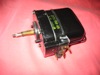
I did a little trick with the red ignition power wire. Instead of connecting it to a terminal 15 fuse, I connected it to a relay, which is energized by terminal SU of the ignition switch harness. Terminal SU is used on all 70s VWs to operate the warning buzzer when the key is left in the ignition and the drivers door is open. On Things, that function is not used, but the ignition switch, common to other VWs, has that feature. On Things, terminal SU provides +12V when the key is inserted. It is possible that the current required by the radio (for ignition power) would make a relay unnecessary, but I would rather protect the electrical contacts in the ignition switch, so I used a relay, just to be safe. A .110 female disconnect (with locking tab) was inserted into the vacant SU cavity of the ignition switch harness to make this work.
Here's a sketch:
Wired this way, the radio will operate with the key in the ignition, but with the ignition switched off.
When the key is removed, the radio turns off.
I had switched to blade type fuses years ago, so I changed some wiring details while the spaghetti was exposed. The 10th fuse now powers the right side dash panel, with individual fuses for the factory power outlet, lighter, radio, amp, and secondary power outlet in the glove box. I changed the glove box light to only operate only with the ignition switched on, because people kept bumping that light and it would be left on overnight.
Here's what it looks like now; behind the large rubber cover is a USB and aux input port:
Good luck, Mondshine
Last edited by mondshine on Tue Jun 10, 2014 2:28 pm; edited 1 time in total |
|
| Back to top |
|
 |
Captain Spalding
Samba Member

Joined: February 19, 2005
Posts: 2519
Location: . . . in denial.
|
| Posted: Wed Jun 04, 2014 9:22 am Post subject: |
|
|
That's a pretty sweet set-up. I was unaware of the SU terminal.
Just to flesh out the why's and wherefore's:
When most of us install a stereo, we have the choice of wiring the radio to switched power (terminal 15) or unswitched power (terminal 30). If the stereo is connected to unswitched power, there is the risk that it will be accidentally left on while the car is unattended, and the battery will be drained. If the stereo is connected to switched power, and one wishes to listen to it while the engine is off but the key is on, there is a risk of burning the points or cooking the coil.
Mondshine's revelation solves both problems. It allows one to sit in the car and listen to music or whatever with the engine off and no risk to the points or coil, and also no risk of walking away having left the stereo on to drain the battery (unless you leave the keys in the car, tisk tisk.)
Thanks for that tidbit, Mondshine!
ETA: both radio knobs mounted vertically on one side of the radio = genius. |
|
| Back to top |
|
|
mkparker
Samba Member
Joined: October 12, 2004
Posts: 332
Location: Sherman, Tx
|
| Posted: Thu Jun 05, 2014 6:11 am Post subject: |
|
|
I like this a lot! Thanks for the great pics and diagrams!
_________________
Michael
Pit Boy 6163 Spec Trophy Truck |
|
| Back to top |
|
|
shum
Samba Member
Joined: January 03, 2012
Posts: 44
Location: santa cruz
|
| Posted: Thu Jun 05, 2014 10:56 pm Post subject: |
|
|
Thank you so much for the detailed post!
Although aware of the warning buzzer circuit, I would never ever have connected the dots so to speak and come up with the idea to repurpose it to actuate a relay. Bravo! Has me thinking of what else one might do with this new found connection (pun intended).
_________________
57 rag top, 67 bug, 73 Thing
70 Bronco U14, 73 Bronco U15
61 R69S/2 BMW, 73 R75/5 BMW |
|
| Back to top |
|
|
surfarii
Samba Member

Joined: November 26, 2006
Posts: 307
Location: Hawaii
|
| Posted: Fri Jun 06, 2014 1:57 am Post subject: |
|
|
That is now my dream set up...Thanks Mondshine now I got to have it 
The SU terminal is a great idea. I have mine set up with a hidden remote switch so I can listen without the key in and eliminate the risk of burning points. This is a way better solution.
As good as my system sounds I have grown used to listening to Pandora off my iphone in my modern truck. My Thing is set up for an Ipod and I am way too inconvenienced to change play lists on my old school ipod. haha #FirstWorldProblems
Thanks for sharing |
|
| Back to top |
|
|
retrosoundusa
Samba Member
Joined: February 23, 2009
Posts: 11
Location: Chino, California
|
| Posted: Mon Jun 09, 2014 3:42 pm Post subject: Re: Radio Installation |
|
|
Love your install Mondshine!! Keep up the innovative installs, this is why we made the radio this way!! --- Retrosound!
| mondshine wrote: |
Heres a slightly different radio installation in my 74 181.
I was looking for a Bluetooth radio that could sync and charge my phone, and look decent in my car. I chose the RetroSound Model 2 for these features and its flexible mounting possibilities. My Thing is a 74, so it has a big defroster hose from the center tunnel to a center plenum, which distributes air to the defroster vents. This is a pretty bulky assembly, leaving very little mounting depth behind the right side dash panel.
The RetroSound radios are the only radios I know of with a separable face, to allow remote mounting of the radio chassis. A special multi pin cable provided by RetroSound connects the radios chassis and face. The radios knobs are interchangeable, and are connected to the radio chassis by standard 4 conductor telephone handset plugs.
Here's a photo of the radio face:
The aluminum bracket is home made. It is attached to the dash panel with 4 screws which have been welded to the back of the panel. Double nuts permit depth adjustment.
The radio's chassis (about 4x5x2) is buried (mounted) way over in the left side of the dash, above the fuse panel and behind the headlight switch.
Wiring the radio is straightforward. Theres a yellow wire for constant fused power, a red wire for ignition power, a blue wire for remote amp turn-on, and a black wire for ground.
I did a little trick with the red ignition power wire. Instead of connecting it to a terminal 15 fuse, I connected it to a relay, which is energized by terminal SU of the ignition switch harness. Terminal SU is used on all 70s VWs to operate the warning buzzer when the key is left in the ignition and the drivers door is open. On Things, that function is not used, but the ignition switch, common to other VWs, has that feature. On Things, terminal SU provides +12V when the key is inserted. It is possible that the current required by the radio (for ignition power) would make a relay unnecessary, but I would rather protect the electrical contacts in the ignition switch, so I used a relay, just to be safe. A .110 female disconnect (with locking tab) was inserted into the vacant SU cavity of the ignition switch harness to make this work.
Here's a sketch:
Wired this way, the radio will operate with the key in the ignition, but with the ignition switched off.
When the key is removed, the radio turns off.
I had switched to blade type fuses years ago, so I changed some wiring details while the spaghetti was exposed. The 10th fuse now powers the right side dash panel, with individual fuses for the factory power outlet, lighter, radio, amp, and secondary power outlet in the glove box. I changed the glove box light to only operate only with the ignition switched on, because people kept bumping that light and it would be left on overnight.
Here's what it looks like now; behind the large rubber cover is a USB and aux input port:
Good luck, Mondshine |
|
|
| Back to top |
|
|
bald_dude43
Samba Member

Joined: May 15, 2014
Posts: 107
Location: Ewa Beach Hawaii
|
| Posted: Mon Jun 09, 2014 7:05 pm Post subject: |
|
|
| Damn Mondshine .... just one more project I now want to undertake! Thanks for the info. |
|
| Back to top |
|
|
doublecanister
Samba Member

Joined: September 23, 2008
Posts: 1184
Location: Richmond, Va
|
| Posted: Wed Jun 11, 2014 9:53 am Post subject: Very Nice |
|
|
 Very nice setup Mondshine, dude did you work for VW? Very nice setup Mondshine, dude did you work for VW? 
You should have!
I've been mulling a radio upgrade myself, mine only plays radio and cd's and would love to have a aux port for the ipod.
the prev owner installed mine under the glove box, not a bad install as the radio has a removable face, I'd planned on upgrading but I like this wire method.
btw, did you use a special relay of any sort?
ive not done much with relays before, except on the Mustang, the ignitor 2 is now wired via 12v relay since I burned up the last ignitor (learned the hard way).
Thanks for the info man!
T
_________________
****************************************
2020 - Mustang Eco Boost [High Performance]
1973 - Thing
1966 - Mustang GT- Fastback
1951 - Ford F1 pickup Flathead V8 |
|
| Back to top |
|
|
mondshine
Samba Member
Joined: October 27, 2006
Posts: 2769
Location: The World's Motor Capital
|
| Posted: Wed Jun 11, 2014 12:19 pm Post subject: |
|
|
Thanks for the kind words.
Double-
The relay might be unnecessary. I assume that inside the radio, there is a similar device to turn on the radio when the ignition is switched on. However, to be certain that the SU contact is not overloaded, I chose to use a standard Bosch relay. The sketch shows a SPDT relay (with contact 87a), but it is unnecessary in this situation; just the relays I keep in stock. A standard SPST relay would do the same job without the need to insulate terminal 87a which is unused, but hanging out in the open, and is connected to terminal 30 (battery+)
when the relay is not energized.
Did I work for VW? No, I was a commercial photographer, so I pretty much goofed off for my entire career. Now that I'm retired, I can take goofing off to a whole new level. (It's good to be the king!)
By the way- You should definitely drive to Branson next month. Getting there is half the fun; it's not just a drive, it's an adventure! |
|
| Back to top |
|
|
Captain Spalding
Samba Member
Joined: February 19, 2005
Posts: 2519
Location: . . . in denial.
|
| Posted: Thu Jun 12, 2014 4:58 pm Post subject: |
|
|
I'm embarrassed to ask, Mondshine - my google-fu must be weak today. Where did you get the .110 female locking non-insulated spade connector?
Also let me offer that, for those as anal retentive as I am, on cars equipped with the ignition key alarm the wiring to terminal SU is solid gray 0.5mm^3 (22 gauge). |
|
| Back to top |
|
|
mondshine
Samba Member
Joined: October 27, 2006
Posts: 2769
Location: The World's Motor Capital
|
| Posted: Thu Jun 12, 2014 5:38 pm Post subject: |
|
|
Captain-
For the last few years, I have used nothing but open barrel crimps. That's what the factory used, and I think they're the only way to go.
I buy my crimp connectors from Susquehanna Motorsports...
http://www.rallylights.com/all/electrical/connectors/crimp.html
These are Hella brand. I'm pretty sure the .110's (2.8mm) were Hella from Susquehanna.
I also buy some high quality Japanese connectors from Eastern Beaver...
http://www.easternbeaver.com/Main/Elec__Products/Connectors/connectors.html
Jim's a Canadian guy, living in Japan. He offers some items I haven't seen available anywhere else, and some I'm sure I could get locally if I tried hard enough. I just prefer to deal with Jim.
I use a Paladin Crimp-All with interchangeable dies; it does a good job.
I know about the gray wire for terminal SU, but I don't stock gray wire so I used black (hope we can still be friends  ) ) |
|
| Back to top |
|
|
Al Capulco
Samba Member
Joined: October 31, 2005
Posts: 532
Location: Northridge, CA.
|
| Posted: Thu Jun 12, 2014 7:45 pm Post subject: |
|
|
| I have the AMP/TYCO connectors. I believe they were the OEM supplier. If you want a couple send me a PM. Or if you don't want to crimp the connector, I have the gray wire with the terminal on it. It has a black stripe, but is the actual wire from the ignition plug, but it is only 2 feet long. |
|
| Back to top |
|
|
Captain Spalding
Samba Member
Joined: February 19, 2005
Posts: 2519
Location: . . . in denial.
|
| Posted: Fri Jun 13, 2014 9:39 am Post subject: |
|
|
| mondshine wrote: |
Captain-
For the last few years, I have used nothing but open barrel crimps. That's what the factory used, and I think they're the only way to go. |
Thanks very much for those sources!
| Quote: |
| I know about the gray wire for terminal SU, but I don't stock gray wire so I used black (hope we can still be friends ) |
"Bring in the fainting couch," he cried, clutching at his pearls. I guess that's okay. I crimp my connectors with a ball peen hammer and a flat rock. 
| Al Capulco wrote: |
| I have the AMP/TYCO connectors. I believe they were the OEM supplier. If you want a couple send me a PM. Or if you don't want to crimp the connector, I have the gray wire with the terminal on it. It has a black stripe, but is the actual wire from the ignition plug, but it is only 2 feet long. |
Thanks, Al. I'll take you up on your kind offer. PM sent. I have the AMP tool, I believe. |
|
| Back to top |
|
|
strelnik
Samba Member
Joined: October 01, 2010
Posts: 352
Location: Michigan
|
| Posted: Thu Jun 19, 2014 5:47 am Post subject: |
|
|
| bald_dude43 wrote: |
| Damn Mondshine .... just one more project I now want to undertake! Thanks for the info. |
I have just received a 100 VAC/ 12VDC AM/FMcassette player with internal speaker that was made like the Telefunken model of the 1950s. You can install a bracket and then remove it like a picnic radio! I would remove it for security's sake, tho.
Sound is great!
Wondering about puitting it in the Thing or buying a Beetle just for this guy.
_________________
L'audace! L'audace! Toujours l'audace! |
|
| Back to top |
|
|
Captain Spalding
Samba Member
Joined: February 19, 2005
Posts: 2519
Location: . . . in denial.
|
| Posted: Thu Jun 19, 2014 2:40 pm Post subject: |
|
|
I did the job last night. It would have taken a smart guy about 20 minutes, but it took me twice that long. Only popped one fuse! There was an issue identifying the terminals on the no-name relay I purchased (next time it's Hella, for sure). And then there's managing the risk inherent in opening that left dash pod and exposing the rat's nest behind. But it's all sorted and works great.
Many thanks to Mondshine and Al Capulco. Now I can scarf down the occasional drive thru meal while listening to the radio, worry free! |
|
| Back to top |
|
|
mondshine
Samba Member
Joined: October 27, 2006
Posts: 2769
Location: The World's Motor Capital
|
| Posted: Fri Jun 20, 2014 7:58 am Post subject: |
|
|
Good to hear Captain-
I know what you mean about the rat's nest. I don't think there is any way to have a "show car" wiring scheme (with beautifully laid out routing) back there short of building a custom wiring harness.
I have a lot of extra stuff behind the left panel; wiring for cruise control, gauges, daytime running light module, a relay to blip the high beams with the headlights off, and oh yes, the chassis of my new radio.
It looks like spaghetti city.
I have put heat shrink tubing over all of the female disconnects at the fuse panel and all switches, and there's a master fuse in the main artery, the heavy red/white line which runs from the starter solenoid 30 to the headlight switch 30 to avoid a catastrophic meltdown.
Good luck, Mondshine |
|
| Back to top |
|
|
|


