| Author |
Message |
t3kg
Samba Member

Joined: June 14, 2006
Posts: 2712
Location: Los Angeles

|
 Posted: Sat Mar 31, 2018 2:16 pm Post subject: Early Type 34 ignition/signal housing rebuild Posted: Sat Mar 31, 2018 2:16 pm Post subject: Early Type 34 ignition/signal housing rebuild |
 |
|
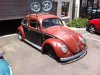
My Type 34's steering column has had a rough life. Everything was working before I removed it, but I'm going to have to rewire the ignition switch and the signal lever at least. Any advice before I jump in?
It's a wonder the ignition circuit didn't short out, seeing as it was clamped between the column and the dash. And dig that vintage cloth electrical tape.
More electrical tape wizardry.
Hack/splice of the signal lever wiring. The screws for the button are missing and it's held in place just by the tension on the wires.
I remember seeing a detailed step-by-step disassembly and reassembly thread not too long ago, but I can't find it despite a lot of searching. If anyone has a link to that thread I would be much obliged!
Scott
_________________
5/62 343
I WAS THERE! The 2017 Type 3 Rally / September 29October 1 / Cayucos, CA
2014: The 2014 Type 3 Rally / October 35 / Cayucos, CA
2011: 50 Years of the VW Type 3 / September 29October 1 / California Central Coast |
|
| Back to top |
|
 |
MonT3
Samba Member
Joined: January 07, 2012
Posts: 1988
Location: South Dakota
|
| Posted: Sat Mar 31, 2018 5:28 pm Post subject: Re: Early Type 34 ignition/signal housing rebuild |
|
|
I'm sure you already have a diagram of the ignition setup there. If I were to rebuild mine all over again (I did my 67 square, looks to be the same), I'd remove the turn signal arm, documenting how its put together and such. This may give you access to loosen the ignition switch. I would take a soldering pen and heat the solder points to the ignition switch to free the wires. This way the internal pieces are intact and the end does not come off when trying to remove the ignition and it comes out as one unit. I can then remove that piece leaving the wires in place. I'd then study and document where the wires travel thru as there are some small cavities they go thru. I'd then document where the wires are connected to the block. I'd remove the wires from the block with a soldering pen. Once the wires are free, pull them all out and start cleaning that thing up for a fresh coat of paint. Hope this helps
_________________
MonT3
67 Squareback
64 Squareback
63 Squareback
Engine rebuild
Trailer rebuild |
|
| Back to top |
|
|
t3kg
Samba Member
Joined: June 14, 2006
Posts: 2712
Location: Los Angeles
|
|
| Back to top |
|
|
gregson1
Samba Member

Joined: December 13, 2004
Posts: 464
|
| Posted: Sun Apr 01, 2018 10:43 am Post subject: Re: Early Type 34 ignition/signal housing rebuild |
|
|
Strip it all down bare, prep and paint it. Replace what's broken, then rebuild.
There's a bearing in there to rebuild or replace, a contact plate that may have been hacked up during your car's importation and can be replaced, and Mario usually has replacement finger switch kits available to fully replace the switch, spring and wiring. You'll need a length of PVC wire housing, as well as a crimper and some new brass ends (that wiring kit I sold you has the brass ends).
Depends on how far you want to go, but the wiring paths inside the housing can also be cleaned up with a Dremel or round file. |
|
| Back to top |
|
|
260KMN
Samba Member
Joined: January 17, 2014
Posts: 236
Location: Devon UK
|
| Posted: Sun Apr 01, 2018 11:48 am Post subject: Re: Early Type 34 ignition/signal housing rebuild |
|
|
| I just did mine, take pictures of everything for reference. I had extra wires on mine which are year/model specific so watch out for that. |
|
| Back to top |
|
|
t3kg
Samba Member
Joined: June 14, 2006
Posts: 2712
Location: Los Angeles
|
| Posted: Sun Apr 01, 2018 1:02 pm Post subject: Re: Early Type 34 ignition/signal housing rebuild |
|
|
| gregson1 wrote: |
Strip it all down bare, prep and paint it. Replace what's broken, then rebuild.
There's a bearing in there to rebuild or replace, a contact plate that may have been hacked up during your car's importation and can be replaced, and Mario usually has replacement finger switch kits available to fully replace the switch, spring and wiring. You'll need a length of PVC wire housing, as well as a crimper and some new brass ends (that wiring kit I sold you has the brass ends).
Depends on how far you want to go, but the wiring paths inside the housing can also be cleaned up with a Dremel or round file. |
Thanks Greg. Yeah, the bearing seems worn and I think I'll have to replace it. I think the flasher button will be OK with a careful rewire but it's good to know that Mario might have replacements in case things go south. The contact plate is good and most of the other parts are there and seem OK. I'm lucky to have all the Type 34-only parts in good shape.
You might know this: Should there be a rubber seal at the top of the column tube, where it meets the housing? I have two parts books one shows a seal up to '67, the other (early) shows no seal. I guess that means there wasn't originally a seal there in '62 but a seal that was introduced later could be retrofitted to earlier cars?
_________________
5/62 343
I WAS THERE! The 2017 Type 3 Rally / September 29October 1 / Cayucos, CA
2014: The 2014 Type 3 Rally / October 35 / Cayucos, CA
2011: 50 Years of the VW Type 3 / September 29October 1 / California Central Coast |
|
| Back to top |
|
|
t3kg
Samba Member
Joined: June 14, 2006
Posts: 2712
Location: Los Angeles
|
|
| Back to top |
|
|
OvalinAz
Samba Mini Tech
Joined: June 09, 2009
Posts: 1076
Location: AZ

|
| Posted: Sun Apr 01, 2018 8:01 pm Post subject: Re: Early Type 34 ignition/signal housing rebuild |
|
|
ill find the link to the guys posts that another member told me, not much inf on how to do so, i just did the same thing with my notch column. the worst part was getting the ignition wire group through the housing
_________________
Dad's 4/55 Oval
8/56 Oval
5/64 French Notchback
12/62 French 11 Window Bus
Wedge VW
Pandraggers C.C. |
|
| Back to top |
|
|
gregson1
Samba Member
Joined: December 13, 2004
Posts: 464
|
| Posted: Sun Apr 01, 2018 8:05 pm Post subject: Re: Early Type 34 ignition/signal housing rebuild |
|
|
| I saw the inner steering column seal listed, but I've yet to actually see any remnants of one from the five columns I've pulled apart. I think I asked Mario about it once, but he had none in stock. Maybe ataraxia has one? |
|
| Back to top |
|
|
ataraxia
Samba Member
Joined: March 19, 2010
Posts: 4504
Location: Illinois
|
| Posted: Mon Apr 02, 2018 8:28 am Post subject: Re: Early Type 34 ignition/signal housing rebuild |
|
|
| t3kg wrote: |
| Should there be a rubber seal at the top of the column tube, where it meets the housing? I have two parts books one shows a seal up to '67, the other (early) shows no seal. I guess that means there wasn't originally a seal there in '62 but a seal that was introduced later could be retrofitted to earlier cars? |
That seal, while it has a part number, has never been found in any of the cars I've owned or taken apart (let's be real, pretty much every car I've owned). I think it got a part number and made it to the drawing but wasn't in a car unless it's a very limited production run. I've never found one either in a car or available for sale anywhere. The only thing I can think that it references is the little vinyl donut that goes on the outside of the column tube on top of the carpet. I don't know if those were in the early cars or part of the carpet.
I have contact plates, bearing housings, high beam rebuild kits, etc. if you need parts.
I've found that the only real challenge to rebuilding the column is getting the wires back through the tiny cavity on each side - this is made much easier if you rewire and wait to install the spade connectors until after you've fished the wires through the column head. There's also enough wire on the prefinished wires to snip the spade connectors off and install them after it's fished through. Just make sure you cut them off as close to the existing spade connector as possible.
Here's a visual on my NOS column for reference to wire path back through the column (ignition wires on the back of the switch on one side, indicator wiring on the other side, more or less):
The rest of it is pretty straightforward once you've figured out how to remove/install the ignition switch. |
|
| Back to top |
|
|
gregson1
Samba Member
Joined: December 13, 2004
Posts: 464
|
| Posted: Mon Apr 02, 2018 8:46 am Post subject: Re: Early Type 34 ignition/signal housing rebuild |
|
|
Josh--If you have it out, could you take some pictures and measurements of the wiring that dangles from this part. I'd like to know how long the PVC wire sheathing is, and how long each wire is.
I've used various sizes of round files and a Dremel to clean up the two wiring paths inside the housing to give the wiring a little more room. |
|
| Back to top |
|
|
ataraxia
Samba Member
Joined: March 19, 2010
Posts: 4504
Location: Illinois
|
| Posted: Mon Apr 02, 2018 8:51 am Post subject: Re: Early Type 34 ignition/signal housing rebuild |
|
|
| gregson1 wrote: |
Josh--If you have it out, could you take some pictures and measurements of the wiring that dangles from this part. I'd like to know how long the PVC wire sheathing is, and how long each wire is.
I've used various sizes of round files and a Dremel to clean up the two wiring paths inside the housing to give the wiring a little more room. |
This column is now installed on my car - the pic is about three years old.
If I have to rebuild another column, I'll try the Dremel and use shrink tube on the wires going through the column. Rare that you need to (or can) get only one or two wires through the cavity - might as well make it easier to install/remove! |
|
| Back to top |
|
|
Bobnotch
Samba Member

Joined: July 06, 2003
Posts: 22410
Location: Kimball, Mi
|
| Posted: Mon Apr 02, 2018 12:17 pm Post subject: Re: Early Type 34 ignition/signal housing rebuild |
|
|
| 260KMN wrote: |
| I just did mine, take pictures of everything for reference. I had extra wires on mine which are year/model specific so watch out for that. |
Yup, my 64 T-34 Ghia was like that. The extra wires were for the side marker lights.
_________________
Bob 65 Notch S with Sunroof
71 Notch ...aka Krunchy; build pics here;
http://www.thesamba.com/vw/forum/viewtopic.php?t=249390 -been busy working
64 T-34 Ghia...aka Wolfie, under construction... http://www.thesamba.com/vw/forum/viewtopic.php?t=412120
| Tram wrote: |
| "Friends are God's way of apologizing for relatives." |
| Tram wrote: |
| People keep confusing "restored" and "restroyed". |
|
|
| Back to top |
|
|
t3kg
Samba Member
Joined: June 14, 2006
Posts: 2712
Location: Los Angeles
|
| Posted: Mon Apr 02, 2018 7:43 pm Post subject: Re: Early Type 34 ignition/signal housing rebuild |
|
|
| ataraxia wrote: |
| t3kg wrote: |
| Should there be a rubber seal at the top of the column tube, where it meets the housing? I have two parts books one shows a seal up to '67, the other (early) shows no seal. I guess that means there wasn't originally a seal there in '62 but a seal that was introduced later could be retrofitted to earlier cars? |
That seal, while it has a part number, has never been found in any of the cars I've owned or taken apart (let's be real, pretty much every car I've owned). I think it got a part number and made it to the drawing but wasn't in a car unless it's a very limited production run. I've never found one either in a car or available for sale anywhere. The only thing I can think that it references is the little vinyl donut that goes on the outside of the column tube on top of the carpet. I don't know if those were in the early cars or part of the carpet.
|
Actually I found that the seal is listed in the early book too, it's just not shown in the drawing. Apparently introduced in mid-1963. It's described as a "dichtring für Mantelrohr" or oil seal for the column tube. Maybe it was a dealer fix for problems with bearing grease fouling the electrical contacts?
_________________
5/62 343
I WAS THERE! The 2017 Type 3 Rally / September 29October 1 / Cayucos, CA
2014: The 2014 Type 3 Rally / October 35 / Cayucos, CA
2011: 50 Years of the VW Type 3 / September 29October 1 / California Central Coast |
|
| Back to top |
|
|
t3kg
Samba Member
Joined: June 14, 2006
Posts: 2712
Location: Los Angeles
|
|
| Back to top |
|
|
ataraxia
Samba Member
Joined: March 19, 2010
Posts: 4504
Location: Illinois
|
| Posted: Tue Apr 03, 2018 7:43 am Post subject: Re: Early Type 34 ignition/signal housing rebuild |
|
|
| t3kg wrote: |
| Actually I found that the seal is listed in the early book too, it's just not shown in the drawing. Apparently introduced in mid-1963. It's described as a "dichtring für Mantelrohr" or oil seal for the column tube. Maybe it was a dealer fix for problems with bearing grease fouling the electrical contacts? |
You're referring to 311 415 573, correct? It's #27 in the diagram:
I wonder if that was a part that - based on your theory of attempting to eliminate fouling electrical connections - was eliminated when the ground tab was moved from the column tube to the steering box? Notice that there's a male spade connector at the bottom of the column tube...when that moved (likely between engineering drawings and production), the seal was no longer needed? I've never seen a spade connector at the bottom of a steering column tube other than in the book. Without that spade connector - there's no other electrical to foul if the bearing did leak grease.
I've always found it odd that the end of the steering column tube is open at the steering box end. |
|
| Back to top |
|
|
t3kg
Samba Member
Joined: June 14, 2006
Posts: 2712
Location: Los Angeles
|
| Posted: Tue Apr 03, 2018 8:26 am Post subject: Re: Early Type 34 ignition/signal housing rebuild |
|
|
| ataraxia wrote: |
| t3kg wrote: |
| Actually I found that the seal is listed in the early book too, it's just not shown in the drawing. Apparently introduced in mid-1963. It's described as a "dichtring für Mantelrohr" or oil seal for the column tube. Maybe it was a dealer fix for problems with bearing grease fouling the electrical contacts? |
You're referring to 311 415 573, correct? It's #27 in the diagram:
I wonder if that was a part that - based on your theory of attempting to eliminate fouling electrical connections - was eliminated when the ground tab was moved from the column tube to the steering box? Notice that there's a male spade connector at the bottom of the column tube...when that moved (likely between engineering drawings and production), the seal was no longer needed? I've never seen a spade connector at the bottom of a steering column tube other than in the book. Without that spade connector - there's no other electrical to foul if the bearing did leak grease.
I've always found it odd that the end of the steering column tube is open at the steering box end. |
Yes, #27. It's weird that a part that's listed in the books for cars between mid-'63 and 67 is something no one has ever seen. That's what makes me think it might have been a service part.
I was wondering about the spade connector on the tube in the drawing too. It's also shown in my '61 parts book, so it's a bit of a mystery.
_________________
5/62 343
I WAS THERE! The 2017 Type 3 Rally / September 29October 1 / Cayucos, CA
2014: The 2014 Type 3 Rally / October 35 / Cayucos, CA
2011: 50 Years of the VW Type 3 / September 29October 1 / California Central Coast |
|
| Back to top |
|
|
OKType3Tim 
Samba Member
Joined: April 30, 2011
Posts: 279
Location: Northeast Oklahoma
|
| Posted: Sun May 13, 2018 4:51 am Post subject: Re: Early Type 34 ignition/signal housing rebuild |
|
|
So... for clarification, exactly which wires go down which side of the column?
Do I have them listed correctly below? Do I have the last two at the bottom of the list correct?
Ignition-Red: left side
Ignition-Red/Black-solder: left side
Ignition-Gray: left side
Ignition-Black: left side
Turn signal switch-Brown: left side
Turn signal switch-Brown/white: left side
Bearing-Brown-solder: right side
Turn signal Plate-Black/Green-solder: right side
Turn signal Plate-Black/White-solder: right side
Turn signal Plate-Gray/Red-solder: right side
Turn signal Plate-Gray/Black-solder: right side
Turn signal Plate-Black/Green/White: ?? left side
Turn signal Plate-Gray: ?? left side
(Note: this would be a turn signal plate that supports side marker lights. If no side marker lights then no Gray/Red, Gray/Black or Gray wires from the Turn signal plate.)
_________________
'69 Squareback restoration
'69 Fastback restoration
'66 Type34 |
|
| Back to top |
|
|
ataraxia
Samba Member
Joined: March 19, 2010
Posts: 4504
Location: Illinois
|
| Posted: Sun May 13, 2018 5:41 am Post subject: Re: Early Type 34 ignition/signal housing rebuild |
|
|
| OKType3Tim wrote: |
So... for clarification, exactly which wires go down which side of the column?
Do I have them listed correctly below? Do I have the last two at the bottom of the list correct?
Ignition-Red: left side
Ignition-Red/Black-solder: left side
Ignition-Gray: left side
Ignition-Black: left side
Turn signal switch-Brown: left side
Turn signal switch-Brown/white: left side
Bearing-Brown-solder: right side
Turn signal Plate-Black/Green-solder: right side
Turn signal Plate-Black/White-solder: right side
Turn signal Plate-Gray/Red-solder: right side
Turn signal Plate-Gray/Black-solder: right side
Turn signal Plate-Black/Green/White: ?? left side
Turn signal Plate-Gray: ?? left side
(Note: this would be a turn signal plate that supports side marker lights. If no side marker lights then no Gray/Red, Gray/Black or Gray wires from the Turn signal plate.) |
Yes this is correct. |
|
| Back to top |
|
|
ataraxia
Samba Member
Joined: March 19, 2010
Posts: 4504
Location: Illinois
|
| Posted: Sun May 13, 2018 6:40 am Post subject: Re: Early Type 34 ignition/signal housing rebuild |
|
|
| t3kg wrote: |
| ataraxia wrote: |
| t3kg wrote: |
| Actually I found that the seal is listed in the early book too, it's just not shown in the drawing. Apparently introduced in mid-1963. It's described as a "dichtring für Mantelrohr" or oil seal for the column tube. Maybe it was a dealer fix for problems with bearing grease fouling the electrical contacts? |
You're referring to 311 415 573, correct? It's #27 in the diagram:
I wonder if that was a part that - based on your theory of attempting to eliminate fouling electrical connections - was eliminated when the ground tab was moved from the column tube to the steering box? Notice that there's a male spade connector at the bottom of the column tube...when that moved (likely between engineering drawings and production), the seal was no longer needed? I've never seen a spade connector at the bottom of a steering column tube other than in the book. Without that spade connector - there's no other electrical to foul if the bearing did leak grease.
I've always found it odd that the end of the steering column tube is open at the steering box end. |
Yes, #27. It's weird that a part that's listed in the books for cars between mid-'63 and 67 is something no one has ever seen. That's what makes me think it might have been a service part.
I was wondering about the spade connector on the tube in the drawing too. It's also shown in my '61 parts book, so it's a bit of a mystery. |
Just to update this theory vs. reality bit...Scott found the documentation and I'm posting in the event someone else comes looking for the info.
|
|
| Back to top |
|
|
|


