| Author |
Message |
VW_Jimbo 
Samba Member

Joined: May 22, 2016
Posts: 9960
Location: Huntington Beach, CA

|
 Posted: Sun Feb 10, 2019 5:07 pm Post subject: Re: 77 Standard Resurrection Posted: Sun Feb 10, 2019 5:07 pm Post subject: Re: 77 Standard Resurrection |
 |
|
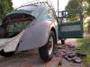
So today, I thought I would take a closer look at the front end. When braking hard, not normal, but severe hard, the car pulls to the left. I was guessing a plugged brake line or a stuck wheel cylinder. So, jacked up the front end and while I spun the tires, I had the youngest push the brake pedal. No issues. So, I then took my torque wrench and tried turning the wheels till the wrench hit the torque value and chimed in. Still nothing found. Brakes held and worked as expected.
I could see and feel a large amount of free play at the steering wheel. Well over three inches. Decided to try and reduce it, if there was some thread left at the steering box. Pulled the spare tire, pulled the cover, brushed off the grime from the adjuster and loosened the jamb nut. Turned the screw about a full turn and then it got hard, backed it off a fourth and reached inside to feel the play. Almost good, still a tiny bit too much play. Gave it another 1/8 of a turn. Checked the steering wheel. Perfect! Popped the cover back on. Still got some play. Damn it!
I then checked the joints. Found a questionable ball joint. Upper, passenger side. I say questionable, because it seems to only have a very small amount of play. Everything is tight. Decided to inject some new grease into the joints. All of the boots are torn, except for the one I am suspect of. Go figure.
Drilled out the top center of the upper ball joint and threaded it for a grease nipple.
Do you see that? Here, look closely. Let me get the dirt off of the joint top.
Now you see it - right? VW Thats an original ball joint. Been many years since I have seen an original VW ball joint.
I then drilled a hole into the cover of the ball joint.
Tapped it and installed a zerk fitting.
Filled it full of grease. The play totally disappeared. So, I took a grease neddle, stuck it on the grease gun and greased all the joints. I had to puncture the boots, but they are all shot anyways. The grease was well received, the front end feels smoother and tighter! I guess I will need to carve out a weekend to replace all the boots. Oh boy.
_________________
Jimbo
There is never enough time to do it right the first time, but all the time necessary the second time!
| TDCTDI wrote: |
| Basically, a whole bunch of fuckery to achieve a look. |
| 67rustavenger wrote: |
GFY's Xevin and VW_Jimbo!  |
|
|
| Back to top |
|
 |
Tom K.
Samba Member

Joined: March 10, 2005
Posts: 1605
Location: Central Pennsylvania
|
|
| Back to top |
|
|
VW_Jimbo
Samba Member
Joined: May 22, 2016
Posts: 9960
Location: Huntington Beach, CA
|
| Posted: Sun Feb 10, 2019 5:19 pm Post subject: Re: 77 Standard Resurrection |
|
|
| Tom K. wrote: |
| Wow - I had no idea this was even an option with old ball joints. I *love* learning new things like this. |
The new ones too!
_________________
Jimbo
There is never enough time to do it right the first time, but all the time necessary the second time!
| TDCTDI wrote: |
| Basically, a whole bunch of fuckery to achieve a look. |
| 67rustavenger wrote: |
| GFY's Xevin and VW_Jimbo! |
|
|
| Back to top |
|
|
VW_Jimbo
Samba Member
Joined: May 22, 2016
Posts: 9960
Location: Huntington Beach, CA
|
| Posted: Tue Feb 26, 2019 11:24 pm Post subject: Re: 77 Standard Resurrection |
|
|
So update time.
Last week, the new tie rod boots were delivered, along with the front disc brake kit. So, this past Saturday I decided to install a the front discs brake kit on the Bug to try and offset the horrible pull to the right when stepping on the pedal.
Here we go!
Jumped right in, first thing in the morning, after we all sat down for a family breakfast. I made waffles and bacon! Mmmmmmm!!!!!!
Okay it is 9am. I go out to the garage and set into motion. First up, get the car up in the air!
Jack stands firmly planted and set nicely under the axle beam. I will often, with the jack under the beam, slightly lower, shake the car to make certain those stands are sitting good. I had one fail on one side of a car, once. That was a OH SHIT! moment that I never wish to repeat. So now, I get the jack stands in place and supporting the weight, lower the jack till it is resting firmly a half inch lower than the contact point and shake the car violently. If it does not fall onto the jack, I will crawl under it. If it falls, we try again!
I then pull the hubcaps and lug nuts, placing them in the trunk, each to their own sides. I also place the wheels under the pan, just in case the car should fall, it will not hit the ground! I am scared of the car falling!
Don't forget to remove the speedometer e clip. I always set that in the hubcap as well. That way I do not lose it!
With the wheels removed and the e clip removed. I take my large adjustable pliers and grip the grease cap firmly. I wiggle it back and forth and "POP"
I then set a clean piece of cardboard under the wheels, so that I can set parts on it to keep the parts clean and the floor. I then remove the axle nut. One on each side. The drivers side is left hand threaded, so be careful! I take my 6mm Allen socket and loosen the clamping bolt. Then with an adjustable wrench, I spin the nut completely free. Don't drop it. Set it on the cardboard.
Oh yeah. For those of you that will read this and still retain your drum brakes. I am pointing out the crap that has been forged into place on the drum, from previous wheel installations. This crap builds up and slightly offsets the rim to drum. Cars came into my shop often with high speed shaking. I would often get paid to fix this, by removing their wheels, scrapping off the drums and inside of the rims, and reinstalling their wheels. That little bit of dirt can cause those high speed wobbles! All you have to do is take a putty knife and scrap that crap off of them before installing the wheels!
Now loosen the brake shoes (if you maintain that adjustment) because those drums do not come off if the shoes are in the correct position. That ridge that forms on the inside of the brake drum get in the way when removing the drum. Take your brake spoon and release the adjuster 5 or more clicks.
Pull the bearing out. I do this by pulling the drum assemble forward, then push it back in. The outside bearing will wait for you, hanging out on the end of the axle. After you push the drum back. Hold it with one hand and grab the bearing with the other. Set the bearing and thrust washer down on the cardboard.
Now pull the drum off.
Ah ha, the brake shoes!
Lets get the shoes off. I use a brake spring retainer removal and installation tool. It connects to a standard 1/4 inch drive tool of your choosing. Set it on the retainer with one hand. Reach around the backing plate and firmly secure the brake retaining pin in place. As you push the pin, also push on the retainer. Get it down about a 1/4 of an inch and turn it 90 degrees. Then slowly release your pressure on the retainer. The spring will expand as you do this. Keep going till all the spring tension is exhausted, then take the retainer, the spring and the pin (remove it from the backing plate by pulling it out till it stops, then sideways and pull. Do it, you will get it!) Place all those parts in the drum or on the cardboard, up to you. I loose stuff, so those small parts go into the drum.
Once the pins are removed, its time to remove the shoes. The springs are extremely strong. Be careful. Trained mechanics have lost finger nails and ripped open their hands due to these springs. However, if you work smart, you can easily overcome their brute strength with leverage.
Lift up on the small spring end of the shoe. You cannot slide the shoe off of the adjuster or the wheel cylinder. The rim of the backing plate will stop your action. You need to remove them without the springs attached, so lift that small end out and away from the adjuster and allow it to return to the rest position. then with that at the center, and no tension from the small spring, remove the small spring. Push the shoes together at that removed spring end and the opposite, large spring end, will almost disengage itself from the car.
The assemble falling off.
I then take the axles. Spray them down with brake cleaner to remove the Cosmoline from shipping. Then I paint them, because I hate rust!
This is a flare end wrench. It is used for brake line removal, transmission lines, fuel lines, anywhere there is a flare nut to be removed. Use them!!! There is one pet peeve I have and that is flare nut rounded over by lazy morons! Seriously, get the right tool! In this case it is to loosen the hose to the wheel cylinder 14mm, 9/16" will work if that is what you have.
Remove the wheel cylinder by removing the 13mm bolt at the backside of the backing plate. Pull it away from the backing plate and, while holding the brake hose, turn the wheel cylinder to completely remove the hose. After it is free, cover the opening of each. You do not want dirt getting into there.
Using a pair of Dikes to straighten out the cotter key. Then I remove the key by grabbing it with the Dikes and leveraging the tool against the nut, pulling the key out. Once out, throw it away. You need to replace it with a new one, EVERY TIME.
Then on to a 19mm to remove the tierod nut.
Oh shit. Wait, I forgot to take the Camber measurements before disassembling! Damn it!!!!!!
So, I put everything back together, except for the wheels and the dust caps. I pulled out the Camber / Caster tool and set it over the axle nut. The magnetic base grabs onto the drum. One then turns the wheel until the small bubble on the tool, at the edge, sits between its own lines. Then you read the measurement bubble you are in need of. For me it is Camber.
Drivers side 1-3/4" (That's out). Passenger about an 1/8 of an inch. Okay, but we can do better! when we reassemble it!
Taking the backing plate off.
Spindle exposed.
I decided to replace the questionable balljoint at this point. I knew it was sloppy. So, I had greased it, but still was unhappy with the play. And since I am right here...
..
Found me the Camber mark and scribed a mark into the spindle, just in case (old habit).
_________________
Jimbo
There is never enough time to do it right the first time, but all the time necessary the second time!
| TDCTDI wrote: |
| Basically, a whole bunch of fuckery to achieve a look. |
| 67rustavenger wrote: |
| GFY's Xevin and VW_Jimbo! |
|
|
| Back to top |
|
|
VW_Jimbo
Samba Member
Joined: May 22, 2016
Posts: 9960
Location: Huntington Beach, CA
|
| Posted: Tue Feb 26, 2019 11:37 pm Post subject: Re: 77 Standard Resurrection |
|
|
Removed the upper and lower balljoint retaining nuts.
Used a tie rod separator and a hammer and popped the upper balljoint. Had to leverage the control arm up and away, to fully clear the balljoint stud.
Then onto the lower balljoint.
Removing the spindle - finally!
I then removed the upper control arm and took it over to the press. Pulled a balljoint out of my stash of parts and pressed in a new upper balljoint. Reinstalled the arm back into the axle tube and installed the new painted, standard height spindle. I then installed the new backing plate.
Here are the rotors getting ready for new wheel bearings.
Looking for the right bearing set to install the bearing races with.
Here it is set in place, ready to be driven into place.
Me setting it into place.
It set in place.
To be continued tomorrow!
_________________
Jimbo
There is never enough time to do it right the first time, but all the time necessary the second time!
| TDCTDI wrote: |
| Basically, a whole bunch of fuckery to achieve a look. |
| 67rustavenger wrote: |
| GFY's Xevin and VW_Jimbo! |
|
|
| Back to top |
|
|
VW_Jimbo
Samba Member
Joined: May 22, 2016
Posts: 9960
Location: Huntington Beach, CA
|
| Posted: Wed Feb 27, 2019 7:25 pm Post subject: Re: 77 Standard Resurrection |
|
|
I then flipped it over and install the small bearing or outer bearing race. Same method.
Both races in. I then paint the interior of the rotors, because I hate rust.
I then pack the bearings with a double tapered grease injection tool. I can set all 4 bearings in at once and force grease into and through them all. I squeeze the grease until it comes out all of the tapered rollers. I then remove each bearing and lightly coat the external portion of the rollers with a swipe of grease. I fill the center portion of the rotor with grease and drop the inner (large bearing into place. I follow that up with the seal. Before installing ANY seal, you must grease the internal portion where the spring is located, or else. If you do not, when you tap the bearing into position, the spring will depart from the seal. You may see this or not. If you do, you are one of the lucky few. If you dont, you will have a horrible grease burning smell down the road and possible a welded on bearing! Seen it a time or two.
Use the bearing driver to set the seal.
Then lightly coat the axle with grease. Dont forget the seal mating area as well,
All lubed and ready!
Now take the rotor and slide it onto the spindle. When you get to the end, slightly rotate and push it home. That last bit is the seal interacting with the mating surface.
Then, while holding the rotor with your weaker arm, reach over with the better one and slide the outer bearing into place, then the thrust washer (radiused edge to the outside).
Then install the retaining lock nut. You then hand tighten the nut into place while rotating the rotor. Once there, grab a big adjustable wrench and lightly tighten the nut while turning the rotor. You want to seat the bearings. This means getting rid of the excess grease and being certain the rollers are fully seated into the races. You should never tighten it so much that it binds up and does not spin. But tight enough that the bearings seat.
Once the bearings are seated and there is a small amount of turning resistance, it is time to set free play at the bearings. Super easy to do, but does take some feel and experience to be proficient at it.
The goal is to have the axle nut tight enough to move the thrust washer with a screwdriver by rotating the blade of the screwdriver against the washer, NOT the bearing. When the nut is tight enough, you will be able to see the thrust washer move slightly with a small amount of force.
When you think it os correct, tighten the 6mm Allen head socket bolt.
Then, install the dust cap.
I then clean the rotor braking surfaces with brake cleaner to get rid of any oil or grease on the rotor. Oily products and brake pads DO NOT mix.
All clean.
I then grab the caliper and make sure the pads are installed correctly. Next, I take my pad spreader and squeeze the piston into the caliper housing.
I then turn the caliper onto the brake hose. You never want to twist a brake hose, because it increases the chance of it separating internally and causing you grief.
Once twisted on all the way. I take that same flare wrench and tighten the hose up on the caliper. I also remove the hose retainer plate at the other end and loosen the flare nut connecting the rigid line to the hose. I do this to minimize twisting the brake line while installing the caliper onto the spindle.
With the hose loose, I install the caliper onto the spindle. I push the caliper tight up against the spindle and gauge the distance of the pads to rotor. I am looking for equal distances. Empi supplies shims to offset the caliper to help equalize the pad to rotor distance. As you can see, this caliper took two shims.
Check the brake line for being twisted and adjust if needed.
Just need to bleed the brakes and go for a test drive!
_________________
Jimbo
There is never enough time to do it right the first time, but all the time necessary the second time!
| TDCTDI wrote: |
| Basically, a whole bunch of fuckery to achieve a look. |
| 67rustavenger wrote: |
| GFY's Xevin and VW_Jimbo! |
|
|
| Back to top |
|
|
Deebs
Samba Member

Joined: June 23, 2018
Posts: 248
Location: Chattanooga, TN
|
| Posted: Wed Feb 27, 2019 7:39 pm Post subject: Re: 77 Standard Resurrection |
|
|
This was really helpful Jimbo. Should be a sticky. I'll be taking my rotors back off after reading this. I was uncertain about how much grease to put inside the rotor, but this takes care of that. Same thing with greasing the inner sleeve where the spring rests.
Gonna have to read more carefully how you seated the races with that screwdriver. Going by the manual, I slid the rotor, outer bearing and thrust washer in towards the spindle until everything was just making contact with one another (bearings and races), and then threaded my spindle nut on until it was just touching the thrust washer. My wheel spins very freely (wondering if too freely, little resistance/drag), and I couldn't find any axial play when trying to push and pull the rotor from the spindle. |
|
| Back to top |
|
|
VW_Jimbo
Samba Member
Joined: May 22, 2016
Posts: 9960
Location: Huntington Beach, CA
|
| Posted: Wed Feb 27, 2019 7:48 pm Post subject: Re: 77 Standard Resurrection |
|
|
Unfortunately, I had to replace the one balljoint. But I was so wrapped up in documenting this process, I forgot. Thankfully, I caught it when I went to place the Camber/Caster tool onto the rotor. Thats when it hit. Ah f#&$!
Back apart the passenger side went. Pulled the control arm off the beam, pressed out the old joint and pressed in a new one. Thankfully, I keep a spare set around.
New one back in the car.
Old one laying on the ground.
I then went back through the brake install.
Next up was resetting the front alignment.Installed the gauge once again and set Camber. Both sides at 0.5 degrees.
Set toe, checked camber. All good.
Went out for a quick spin around the block. All worked great. I need to readjust toe a little bit to get the steering wheel in the right spot. But that is back burner. I am onto a new clutch, before things become ruined.
_________________
Jimbo
There is never enough time to do it right the first time, but all the time necessary the second time!
| TDCTDI wrote: |
| Basically, a whole bunch of fuckery to achieve a look. |
| 67rustavenger wrote: |
| GFY's Xevin and VW_Jimbo! |
|
|
| Back to top |
|
|
VW_Jimbo
Samba Member
Joined: May 22, 2016
Posts: 9960
Location: Huntington Beach, CA
|
| Posted: Wed Feb 27, 2019 7:52 pm Post subject: Re: 77 Standard Resurrection |
|
|
| Deebs wrote: |
This was really helpful Jimbo. Should be a sticky. I'll be taking my rotors back off after reading this. I was uncertain about how much grease to put inside the rotor, but this takes care of that. Same thing with greasing the inner sleeve where the spring rests.
Gonna have to read more carefully how you seated the races with that screwdriver. Going by the manual, I slid the rotor, outer bearing and thrust washer in towards the spindle until everything was just making contact with one another (bearings and races), and then threaded my spindle nut on until it was just touching the thrust washer. My wheel spins very freely (wondering if too freely, little resistance/drag), and I couldn't find any axial play when trying to push and pull the rotor from the spindle. |
Not a screwdriver, that was a bearing race / seal driver. The screwdriver is for checking the movement of the thrust washer when tightening the bearings.
Based off what you wrote, it is too loose. I am pretty confident that you could jack up the car, grab the tire at the top and bottom and pull and push the tire. If it moves more than 1/8 of an inch, it is too loose!
_________________
Jimbo
There is never enough time to do it right the first time, but all the time necessary the second time!
| TDCTDI wrote: |
| Basically, a whole bunch of fuckery to achieve a look. |
| 67rustavenger wrote: |
| GFY's Xevin and VW_Jimbo! |
|
|
| Back to top |
|
|
VW_Jimbo
Samba Member
Joined: May 22, 2016
Posts: 9960
Location: Huntington Beach, CA
|
| Posted: Wed Feb 27, 2019 8:59 pm Post subject: Re: 77 Standard Resurrection |
|
|
Got back from the brake test drive and ate lunch, while the engine cooled down.
Went out after lunch and jacked the car up in the air on the ass end of the Bug. The Bug has low power, seems to me that the clutch disc has to be slipping and I know it has an oil leak from the rear main seal. It would be nice to drive with a good clutch that actually allows the car to accelerate at a better speed, instead of a lot of noise and no go!
Pulled the engine out, pulled the clutch and here we go.
The tranny, with oil sitting in the bottom of the bell housing.
Removed the pressure plate to look at the disc. Looking at the clutch, it had been recently changed out, but the rear main oil seal leak did it in! Sorry no picture of the old disc. But it explains why it had no get up and go!
Pulled the flywheel, so that I could replace the RMS. Here is the new one.
I cleaned the seal area at the case to an oil free surface, both inside where the seal goes and the exterior lip area.
Back filled the spring area with grease to be certain the spring does not go falling out during the install.
I then coat the outside with Ultra Copper. Acts like a lubricant and locks the seal in place.
Then just push it in with your fingers. You do not need the special tool. Just be sure to push it into the case until you can fully see the chamfer of the seal opening. Then wipe the excess silicon off of the case. Should look like this when finished.
You also need to replace the graphite o-ring in the flywheel.
Then clean that area up. Oil the O-rings up and install it into the flywheel.
For this car, the flywheel clutch surface was good. No ridges, no hot spots, just grimy. So, I took the sanding disc and knocked the gloss off of it. Most times, the flywheel needs to be surfaced at a machine shop. This one looks like it had 20 miles on it. It goes along with the brand new oil soaked clutch disc!
I then cleaned the pilot bearing and inspected it. All checked out okay. I greased up the bearing. That is the amount of grease that is needed, no more, no less.
Just stick your finger in the hole and twist it back and forth, several times. Feel the bearing. If it is rough, change the gland nut.
Wipe off any excess grease and clean the threads.
I then put a drop of oil on the threads, wipe off the mating areas of the crank and flywheel. I reinstall the flywheel and install the Gland Nut. Install the flywheel holding tool and torque it down. I go to 255 on stock engines. You do what you want to do.
Pressure plate and disc are up next. I grab my alignment tool. An input shaft from a tranny. Works awesome and cost me nothing! That is the best kind of tool!
Clutch installed!
Now onto the tranny side of things.
Oil is everywhere, so a good cleaning is in order. I use Simple Green, undiluted. The remnants are dumped into the parts cleaner through cheesecloth.
All clean!
Grease up the pads on the throw out arm. A tiny amount is all that is needed.
Little bit of grease on the Throw Out Bearing (TOB) collar. Very light coat.
Light coat inside the TOB, just to fill the recesses.
Then onto the throw out arm.
Then slide the engine in. This is how I do it.
Got it back in and still need to drive it. Cleaned up my tools and was inside eating dinner at 10pm. Guess I got carried away,
_________________
Jimbo
There is never enough time to do it right the first time, but all the time necessary the second time!
| TDCTDI wrote: |
| Basically, a whole bunch of fuckery to achieve a look. |
| 67rustavenger wrote: |
| GFY's Xevin and VW_Jimbo! |
|
|
| Back to top |
|
|
vamram
Samba Member

Joined: March 08, 2012
Posts: 7300
Location: NOVA
|
| Posted: Thu Feb 28, 2019 8:49 am Post subject: Re: 77 Standard Resurrection |
|
|
Jimbo, love the write up about the brakes and replacing the clutch. Those are great stand-alone threads on those procedures alone, aside from your 77's refresh!
Where can one get the bearing race driver tool?
Víctor
_________________
Eventually, "we are what we pretend to be.
Give peace a chance - Stop Russian-Soviet Aggression!!
'74 Super 9/16 - present, in refurb process.
'73 Super - 6/18 - Present - Daily Driver!
'75 Super Le Grande...waiting it's turn in line behind '74.
Click to view image
Save the Supers!! |
|
| Back to top |
|
|
VW_Jimbo
Samba Member
Joined: May 22, 2016
Posts: 9960
Location: Huntington Beach, CA
|
| Posted: Thu Feb 28, 2019 12:29 pm Post subject: Re: 77 Standard Resurrection |
|
|
| vamram wrote: |
Jimbo, love the write up about the brakes and replacing the clutch. Those are great stand-alone threads on those procedures alone, aside from your 77's refresh!
Where can one get the bearing race driver tool?
Víctor |
Victor,
Thank you for the kind words! I started thinking that I need to start sharing more of my hands on knowledge, in pictures. I figure the next group of people, which interacts with old Bugs will not have had the opportunity to know what original was like, or how it all went together. Thought I might start documenting the processes.
The OTC driver tool set, is aluminum and came from a MAC tool truck, from back in the 1980s. I am sure that there is a similar unit on Amazon. Let me go look and see what I can search out for you.
Here you go;
https://smile.amazon.com/OTC-4507-Bearing-Race-Dri...mp;sr=8-28
_________________
Jimbo
There is never enough time to do it right the first time, but all the time necessary the second time!
| TDCTDI wrote: |
| Basically, a whole bunch of fuckery to achieve a look. |
| 67rustavenger wrote: |
| GFY's Xevin and VW_Jimbo! |
|
|
| Back to top |
|
|
sjbartnik
Samba Member
Joined: September 01, 2011
Posts: 5995
Location: Brooklyn
|
| Posted: Thu Feb 28, 2019 12:58 pm Post subject: Re: 77 Standard Resurrection |
|
|
Once you finish up with the front end you may want to re-visit the steering box adjustment. That should be the last thing you play with after eliminating other sources of play in the front end.
The steering box adjustment needs to be made with the front wheels off the ground and with the steering wheel turned 90 degrees off center in either direction.
Then loosen the locknut, back the screw off a turn, then turn it in until you feel it just contacting the top of the roller shaft. Don't crank it down beyond that or you can damage the steering box really easily. The adjustment is only to keep the roller shaft from moving up and down in the housing (the play) rather than moving left or right.
It will never quite be tight like a modern car - up to 1 inch of play at the steering wheel is within spec.
EDIT: P.S. I love the photo-documented how-to!
_________________
1965 Volkswagen 1500 Variant S
2000 Kawasaki W650 |
|
| Back to top |
|
|
VW_Jimbo
Samba Member
Joined: May 22, 2016
Posts: 9960
Location: Huntington Beach, CA
|
| Posted: Thu Feb 28, 2019 2:25 pm Post subject: Re: 77 Standard Resurrection |
|
|
| sjbartnik wrote: |
Once you finish up with the front end you may want to re-visit the steering box adjustment. That should be the last thing you play with after eliminating other sources of play in the front end.
The steering box adjustment needs to be made with the front wheels off the ground and with the steering wheel turned 90 degrees off center in either direction.
Then loosen the locknut, back the screw off a turn, then turn it in until you feel it just contacting the top of the roller shaft. Don't crank it down beyond that or you can damage the steering box really easily. The adjustment is only to keep the roller shaft from moving up and down in the housing (the play) rather than moving left or right.
It will never quite be tight like a modern car - up to 1 inch of play at the steering wheel is within spec.
EDIT: P.S. I love the photo-documented how-to! |
Thank you sjbartnik, for all of the reply.
I started in on that conversion (I actually had the drums off and one of the backing plates hanging when I thought that a "how to" might be of use to someone, sooner or later. I did the brake how-to and thought the same thing with the clutch.
That photo documentation really takes you out of the moment. A job that would have taken 1 hour, maybe 2. Took me 5 hours. I ended up assembling and forgetting to take a picture. So, I would disassemble, stage the picture and start reassembling. Only to forget again. Took a long time!!!
We all read about everyone working on their cars, but very few document the process. Being formally trained, I thought that I would document the means and methods I was taught, for everyone to use as a basis to their own project(s). I don't know everything, but I have completed quite a bit, amongst some OLD timers. Guys that were in there 50s when I was in my late 20s. Me wrenching in my bay right next to the "old man". Now, I would say I am the old man! Damn it. The difference beyond that is they would teach nothing. All I could do was watch or hold something for them. But hey, I learned a ton!!!!!! I learned to teach!
Again, thank you!
_________________
Jimbo
There is never enough time to do it right the first time, but all the time necessary the second time!
| TDCTDI wrote: |
| Basically, a whole bunch of fuckery to achieve a look. |
| 67rustavenger wrote: |
| GFY's Xevin and VW_Jimbo! |
|
|
| Back to top |
|
|
VW_Jimbo
Samba Member
Joined: May 22, 2016
Posts: 9960
Location: Huntington Beach, CA
|
| Posted: Sun Mar 03, 2019 7:41 pm Post subject: Re: 77 Standard Resurrection |
|
|
Well, today was a finish up stuff from last weekend. After getting the Bug put back together, late last Saturday night, it sat until this morning. I finished installing the motor and reconnecting everything. Reset the basics and went out on a test drive. All was good.
So, moved onto the next item. A poor grounding issue. I have noticed during my time working on the systems, my voltage numbers change by .5 - .8 volts. It has been in the back of my mind, but knew I had to wait till it was running.
Well today was that day and what a great find! I was expecting to spend the entire day, removing ground wires, cleaning them, cleaning the mating surface, squeezing some dielectric grease onto the area and tightening the fastener. Typically I spend four or so hours on that, but this was different. It was the first time that I got under the car, on the first attempt and found the over ruling issue!
Do you see it?
Here, I will circle it for you.
Here is a close up of it. See how loose that connection is and all the crap in between the layers? You can actually see the threads of the stud between the cable eyelets.
Well, to fix it. I took it apart and wire brushed all of the contributing members. I went through, with a brass brush, and cleaned everything up. I applied dielectric grease to all mating surfaces and tightened it all down.
_________________
Jimbo
There is never enough time to do it right the first time, but all the time necessary the second time!
| TDCTDI wrote: |
| Basically, a whole bunch of fuckery to achieve a look. |
| 67rustavenger wrote: |
| GFY's Xevin and VW_Jimbo! |
|
|
| Back to top |
|
|
VW_Jimbo
Samba Member
Joined: May 22, 2016
Posts: 9960
Location: Huntington Beach, CA
|
| Posted: Sun Mar 10, 2019 11:36 pm Post subject: Re: 77 Standard Resurrection |
|
|
Well, lets add another full day of fun to the story!
The car has sat outside for the last week, due to the rains. The interior remained dry, so that is a plus! However, when I got in it this morning to drive it into the garage, lets say, I was less than happy with its responsiveness, both in starting and running. Acting like it has a giant vacuum leak.
I know that I have gone through just about each separate area of the intake, replacing hoses, replacing gaskets, hell, even replaced the damn air boot! There should be nothing left. But as always, I start with the basics first, progressing in the direction which the tests lead me in. No shortcuts - ever!
Started off with a semi valve adjustment. I did drive the car into the garage, but it ran for maybe 2 minutes. Although I know it is enough to not be .006 anymore, I do know about how far from .006 it should be. But I am not looking for .006 anyways. I am looking for something out of place causing me an issue. So, in reviewing the valve gap, I found nothing out of place. Everything seemed like a car that has been started and driven for a few minutes.
Fired it up and let it get to normal temperature. I performed a complete compression test. in order, 1 - 4, 125, 125, 120, 125. I do not think it can get any better than that. This seems like the perfect engine, at this point.
Put the plugs back, connected a fuel pressure gauge, once again to the Cold Start Valve and found the fuel pressure to be as it was last time I checked it, 28psi. Removed the vacuum hose to the regulator and got 36psi. All good. I removed the gauge and opened up the distributor. I checked the cap and rotor, All good. Turned the engine till the eccentric in the distributor was at full lift and measured .016 gap at the points. Checked the vacuum can and movement with a vacuum pump and again, all is good. Man, finding nothing sucks, but at least I know it is none of these items.
Assembled everything back together and started the car up. Man this sucks. It just is not running right!!! WTF is wrong with this thing. Just a complete lack of power and no pull on acceleration.
I get it fired up again. Get it up to temperature and recheck the timing. All good! The distributor advances as it should, and falls within spec. At this point, I am at a loss, then I hear something. I happened to drop my tiny screwdriver near the 1,2 side of the engine. It was when my ears passed by the engine compartment, I heard it! It is a vacuum leak!!!! Now, I am really confused! I know what I am hearing and now cannot turn it off. It is screaming into my ear. But I cannot pinpoint it. I break out the good ol carb cleaner and start methodically shooting bursts of cleaner into selected zones of the engine intake areas. 3/4 injector side - good. Head to manifold - good. Injector seals - good. intake boot 1,2 side - good. 3/4 head to manifold - good. Injector seals - good. Intake boot - a very slight reaction. Almost unnoticeable. It was so faint. I get a longer straw attached to the can and I install a breather hose to the air filter intake that starts on top of the top of the car, so that stray Hydrocarbons do not get sucked into the intake, faking me out. (This aint my first rodeo - I have spent too many hours chasing self inflicted vacuum leaks). I set the idle as low as I can get the car to go, without it stalling. I then aim at the area in question - immediate response. A surge up into the 1000s from 600 or so!!! I have my target in sight!
Out comers the passenger side manifold retaining nuts. Out comes the manifolds passenger side tubes - everything looking good. I then reach into the void and twist off the intake connecting hose.
Check this out....
That right there is a torn boot. That tear was at the five oclock position, out of sight and hard to get to. Good ol carb cleaner!
Since I have the boot and manifold off, might as well see what the intake looks like.
Pulled a boot out of my stock and replaced it.
Reassembled everything and started it up. WOW!!! What a huge difference! The car idles and really low. I had to crank it up several turns.
Well, with that accounted for, I went for a quick test drive.
Still a dog! WTF!!!!! What am I missing...
.something.
Did some brain storming and came up with the AFM has to be out of adjustment. Maybe someone fiddled with the settings to offset another issue.
_________________
Jimbo
There is never enough time to do it right the first time, but all the time necessary the second time!
| TDCTDI wrote: |
| Basically, a whole bunch of fuckery to achieve a look. |
| 67rustavenger wrote: |
| GFY's Xevin and VW_Jimbo! |
|
|
| Back to top |
|
|
VW_Jimbo
Samba Member
Joined: May 22, 2016
Posts: 9960
Location: Huntington Beach, CA
|
| Posted: Sun Mar 10, 2019 11:58 pm Post subject: Re: 77 Standard Resurrection |
|
|
Well, I am seeing my situation, in two ways, regarding the AFM or Air Flow Meter. I can either purchase a rebuilt AFM or try and get the one I have working. I figure I have nothing to lose trying, because if I break it, I will still have to purchase one. So, with nothing to lose, lets proceed forward.
Man, I now have to dig deep, way back in the recesses of my brain. I need some information that I know, but have not used in well over 20 years. Back in the day I was an air cooled fuel injection wizard. I could make these cars dance with a twist of the screwdriver, a four gas analyzer, a timing light and someone else's money! Since it is my own money, lets see if I can do it without a four gas analyzer! I am pretty good on tuning by ear, plus I have nothing to loose. Worst case is I have to beg a shop in town that I take the trucks and cars to for service, for a hour on their gas analyzer.
Lets get started, get out your note book, because this is not written anywhere that I am aware of.
I start with removing the AFM and air cleaner assembly from the car.
And then separate the air cleaner portion from the AFM.
I then remove the cover by gently prying it off with a prybar. GENTLY. Work around the edges till it lets go.
See, in tact and easily reinstalled - later.
What you see within the cavity that cover was protecting is the air fuel ratio potentiometer. As the air flows from the front to the back of the meter, it encounters a large flat plate of metal. That metal plate is like a door on a set of hinges. It pivots, radially, moving a set distance based off of the amount of air flowing through the meter. This air is "metered" air, due to the fact that the flap moves and creates a digital signal for the computer to use, for changing the amount of fuel to the cylinders.
With the cover removed, there are three separate adjustments that can be made.
The three mounting screws which attach and secure the contact plate have larger holes already drilled through the plate for fine tuning by the factory. Loosening these screws and relocating the plate has a large impact on the vehicle. It changes the starting and ending positions of the swing arm and also change the arch of the swing. This has a predictable but odd reaction from the meter. Your old values become useless, as new values are now the over riding variable. This sets the starting point either lower or higher in resistance and also skews the top end numbers. Moving the plate can be frightening, because there is no certainty to it without a tool for measuring this.
However, based off of my experiences, moving the plate a 1/16 in any direction has very little impact on the drivability of the vehicle. What it does do is allow for new surface areas of the contact surface to be used. Since these slowly wear out. On this board there are two large "Whiteish" streaks, exactly in line with the arch from the contact. Those "Whiteish" streaks are from the needle having moved across the board many times and wiped away the protective coating. Adjusting the board to allow a new track to be had is a real improvement for flat spots and other odd drivability issues. I reset this board due to the two white arches at the left of the board. I am fairly certain they would be wearing through in several more months.
This is for increasing the mixture leaner is Clockwise (CW) and richer is counter clockwise (CCW). I need to increase the fuel in the mixture as the car was running way too lean, so CCW it goes. I moved the black plastic maybe an 3/32" to the right. This will increase the mixture over the entire range fairly evenly. Very simple adjustment, but getting it wrong is a pain!
This next adjustment has a dramatic effect on the overall running of the vehicle. Again, for increasing the mixture leaner is Clockwise (CW) and richer is counter clockwise (CCW). I need to increase the fuel in the mixture as the car was running way too lean, so CCW it goes. I moved the black plastic gear looking thing 5 teeth CCW. That yellow mark was at the metal contact plate before I adjusted it. It is now down further on the assembly. To move it you pull back that copper locking spring finger and rotate the gear with a screwdriver. This is the tension of the spring which holds the meter's flap shut and also creates resistance as air rushes into it. I needed to relieve the pressure just a fractional amount.
Now, I know what you are thinking. How does one do this sitting in there garage? Great question. My response is - you do not do it, unless you really, I mean REALLY, have the skills to do it. If you do not have the skills, you are sitting there right now going "this is so cool", if you have the skills, you are sitting there right now going, "this guy knows his shit and I am not touching that - ever!" That is the difference. If you are the later, go for it.
Now for the method I use to set these variable s up with. I get the meter installed, facing up so that I can easily access the sweeping arm.
I then start the car up, after it has been previously warmed up, and with one finger, at idle, I pull and push the swing arm, listening to the reaction from the engine. I move it only a 1/4" at most in both direction. Beyond that and there is something larger at play. Go find that and return. Based off of the reaction I either richen the screw on the arm or lean it out.
This screw.
After that, put it all back together.
In this case, after resetting these adjustments, the car ran perfectly. Better than it has ran since I have been dicking with it. In further review of the device, I believe someone has "rebuilt" it. By that I mean they wiped the dirt off of it and applied some yellow paint to two screws, which one would never touch if they were going to mess with the meter!
Anyways, that todays lesson for FI Bugs! Use the info at your own risk and at your own expense. And remember to not let the smoke out!
Some additional pictures.
I like to see the contact points lined up with the corner of the corner of the green box nearest the contact strip. That has proven to be "the starting point".
Arrows are pointing to the wear marks. You can see the tracks from the wiper. That smaller line is from me. It is after I loosened the boards screws and moved it that 1/32" over. Eliminating the contact to screed across the worn out portions! Ah, good drivability alas!
Close up of the worn spot. I have seen these so bad that the board itself is splintering off on both sides!
Just a shot for some reason. Don't remember anymore!
That concludes the lesson. Until next time!
_________________
Jimbo
There is never enough time to do it right the first time, but all the time necessary the second time!
| TDCTDI wrote: |
| Basically, a whole bunch of fuckery to achieve a look. |
| 67rustavenger wrote: |
| GFY's Xevin and VW_Jimbo! |
|
|
| Back to top |
|
|
unclewede
Samba Member

Joined: May 01, 2015
Posts: 374
Location: Oxnard, CA
|
| Posted: Tue Mar 12, 2019 11:02 am Post subject: Re: 77 Standard Resurrection |
|
|
Where was this 3 years ago when I was FOLLOWING ALONG when someone else did it for my son's 77????
Great job! I feel good that you did many of the things I had done, to get it to DD for my son. We still need to work on the sunroof, it was working GREAT until I had someone put in a new headliner and they used drill-guns to replace screws and cracked plastic. Now we are using PVC caps to hold up the back end of the roof and keep the rain out. |
|
| Back to top |
|
|
Buggeee
Samba Member
Joined: December 22, 2016
Posts: 4408
Location: Stuck in Ohio
|
| Posted: Tue Mar 12, 2019 12:02 pm Post subject: Re: 77 Standard Resurrection |
|
|
| VW_Jimbo wrote: |
Well, I am seeing my situation, in two ways, regarding the AFM or Air Flow Meter. I can either purchase a rebuilt AFM or try and get the one I have working. I figure I have nothing to lose trying, because if I break it, I will still have to purchase one. So, with nothing to lose, lets proceed forward.
|
Very nice write-up Jimbo! Very nice. This AFM stuff is popular in the Vanagon Samba topic.
Here is a third-party link to a good write-up of the tuning procedure with a deep dive into whats happening and why:
https://itinerant-air-cooled.com//viewtopic.php?t=7761
Searching this issue you will find that some people try to get to fresh carbon track area on the board by bending the copper arm that sweeps on it. DO NOT DO IT. There are more than a few write-ups of how to put more of a zig-zag in the shape of the arm to pull it to a fresh arc but DO NOT DO IT. The problem that results is that the pressure of the copper arm on the carbon track is soooooo delicately precise that the slightest alteration results in it scratching a new path through it in very short time (ask me how I know).
So Jimbo's loosen the screws and move the whole board is the better way to attempt the "rebuilding". From many threads in the Vanagon area, it seems that the carbon track cannot be re-coated and the potentiometer board itself cannot be replicated so the theory is that the "rebuilt" units are simply doing Jimbo's process plus a good cleanup.
Next, on replacements. There may be alternatives. I have a write-up in my Vanagon thread on using a 77 Bus AFM in my 83 air-cooled Vanagon.
Also, right now I am running my Vanagon on a an AFM for a 1981-1983 Renault Fuego R18i (Bosch Air Flow Sensor Meter T06 79443 dp). Those are built by Bosch, but because there is no Samba Cult for Renault cars they are a fraction of the cost of the VW AFMs -whether NOS, rebuilt, or used. It was a tad rich across the spectrum and I tuned it lean with the same methods Jim describes, following the procedure in the Itinerant link, above.
Here is a link to the page on my Vanagon build thread where I am going down the rabbit hole on the AFM. The same, or similar, alternatives could be sorted out for a Beetle I am sure. Bosch supplied everyone.
https://www.thesamba.com/vw/forum/viewtopic.php?t=...;start=100
All the AFMs look like direct swaps dimensionally and the tuning procedure got the thing dialed in for me. The real distinction seems to come in with the number of pins for the wires in the connection to the ECU.
_________________
1966 Sportsmobile Camper https://www.thesamba.com/vw/forum/viewtopic.php?t=...mp;start=0
72 Super Duper http://www.thesamba.com/vw/forum/viewtopic.php?t=672387
(adopted out) 61 Turkis Pile https://www.thesamba.com/vw/forum/viewtopic.php?t=728764
| SnowDaySyncro wrote: |
| Every setback is an opportunity to learn stuff and to buy new tools. |
|
|
| Back to top |
|
|
VW_Jimbo
Samba Member
Joined: May 22, 2016
Posts: 9960
Location: Huntington Beach, CA
|
| Posted: Tue Mar 12, 2019 10:25 pm Post subject: Re: 77 Standard Resurrection |
|
|
| Buggeee wrote: |
| VW_Jimbo wrote: |
Well, I am seeing my situation, in two ways, regarding the AFM or Air Flow Meter. I can either purchase a rebuilt AFM or try and get the one I have working. I figure I have nothing to lose trying, because if I break it, I will still have to purchase one. So, with nothing to lose, lets proceed forward.
|
Very nice write-up Jimbo! Very nice. This AFM stuff is popular in the Vanagon Samba topic. |
Thank you! I guess those 3 or 4 years taking classes at the Bosch training center are still paying off!
Yes, I have seen that write up before. Really a good write up. I like the illustrations too.
In the classes we were taught how to fine tune with a four gas analyzer. But they also taught that you were never to remove the cover. It was only for the factory techs. But they went through the why and how. I just put 2 and 2 together and did what I wanted to. Learned a ton doing it!
I worked on many Buses and Vanagon. Rebuilt several Waterboxers through the early years. Very familiar with their systems. You ever have a question, PM me. I will do my best.
_________________
Jimbo
There is never enough time to do it right the first time, but all the time necessary the second time!
| TDCTDI wrote: |
| Basically, a whole bunch of fuckery to achieve a look. |
| 67rustavenger wrote: |
| GFY's Xevin and VW_Jimbo! |
|
|
| Back to top |
|
|
|


