| Author |
Message |
Floating VW
Samba Member

Joined: April 28, 2015
Posts: 1596
Location: The South Zone

|
 Posted: Sun Jan 02, 2022 2:51 pm Post subject: CHT Sensor - Alternate Locations Posted: Sun Jan 02, 2022 2:51 pm Post subject: CHT Sensor - Alternate Locations |
 |
|
I want to start by saying that I am aware there are several other threads that have also dealt with this subject, such as these here:
https://www.thesamba.com/vw/forum/viewtopic.php?t=...mp;start=0
https://www.thesamba.com/vw/forum/viewtopic.php?t=129036&highlight=cht+sensor+location
https://www.thesamba.com/vw/forum/viewtopic.php?t=745116&highlight=cht+sensor+location
https://www.thesamba.com/vw/forum/viewtopic.php?t=424332&highlight=cht+sensor+location
But I feel these threads were all rather lacking in useful data. In fact, the main reason why I wanted to start this one is that almost all of the others were basically three or four pages of people telling the OP to stop being a dumbass and just put the damn sensor ring under the #3 plug.
Of course, we all recognize the benefits of using the #3 plug as a location for the CHT sensor, and if you want to measure your CHT's this way, nobody is gonna ding you for that. So, please let's not discuss the #3 plug any further, here. There is no need.
Instead, I would like to hear from those of you who went a different direction; how did you do it and what were your results, both good and bad.
I'll start with my own experience:
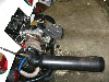
I decided not to go with the #3 plug for a couple of reasons. It makes getting the plug in and out tricky; the plug doesn't sit as deep as it should in the chamber, unless you remove the gasket; and the sensor ring tends to get chewed up over time. But most of all, I don't really care how hot my spark plug is. I did start off with a 14mm ring sensor (in case I ever changed my mind about putting it on the plug), but I had to reshape it to make it fit in the location I chose:
To prevent the sensor from sliding around, I cut out and soldered a piece of copper sheet to the inner part of the "ring", and drilled a hole through the center for a bolt to go through:
If the most important thing to know is the temperature of the valve seats, and the second most important thing to know is the temperature of the hottest spot in the chamber (i.e. the spark plug), then it seems to me the best location for a CHT sensor is right square in the middle of these. On my cylinder heads, there is a little plateau directly beneath the plug and in between the intake and exhaust ports. This is where I drilled a 5mm deep hole and tapped it for an M4 bolt (The hole is not exactly in the center because the shape of the cylinder head makes it very difficult to get a drill in there, but this is not a bad thing. Also, I was a little concerned at first about weakening the material here and possibly causing a crack to form, but the metal is about 25mm thick in this area, and even though you can't see it in this picture, the edges of the hole were later cleaned up and chamfered, so we'll see what happens. I think I'll be fine):
The idea of using JB weld didn't appeal to me, so to clamp the sensor to the head, I fabricated a steel plate and added three layers of gasket material (not visible in this photo) to the back, to insulate it from the sensor. The idea is to not only keep the sensor snug up against the cylinder head, but also to prevent any air flow from cooling the back side of the sensor.
And here is the CHT sensor bolted to the cylinder head. If you notice, the hot junction of the leads is closer to the exhaust valve seat and the spark plug than to the intake valve seat, which is a good thing, in my opinion:
The lead goes through the rear of the cylinder tin, through a small rubber grommet, which makes for a nice, clean installation:
I chose the Micro 1000 dual CHT gauge, which is temperature compensated, to accurately monitor both sides of the engine at the same time (more specifically, cylinders 1 and 3). I calibrated the gauge by dipping the thermocouples in a bath of hot oil, and comparing the reading on the gauge with a digital thermometer. Below 200 degrees F, the gauge is not very accurate, but is spot on between 210 and 400 degrees F, and that suits me just fine. You might also notice that the gauge is in a round, aluminum bezel, instead of a square, black plastic one. That took quite a bit of delicate fabricating on my part, but I wanted it to match my Autometer gauges a little better.
Results?
Let me start with a little caveat here. My engine runs cold, it always has. It was designed and built to do so, and even more so after installing the ram-air cooling ducts and the venturi ring in the fan shroud. So if the following temperatures seem a bit on the low side to you, well, they are on the low side, but that fits in perfectly with what I consider normal for my engine. With that in mind:
Temperature changes on the gauge occur instantaneously (which is something very important to consider when selecting a location for the sensor). In the hot summer months, average highway cruising CHT's are a cool 240 to 260 degrees F. At a sustained full roar in fourth gear on level roads, the heads level off at around 365 degrees F. In the winter months, however, cruising CHT's barely get over 210 degrees F, and this concerns me. To corroborate this, the oil barely gets warm enough to register on the gauge (which starts at 140 degrees F), and that concerns me even more.
Something interesting I noticed is that, once the engine is up to operating temps and the cooling flaps are open, both sides of the engine run almost dead even in temperature. However, at start up, the right bank heats up faster than the left, but only until the flaps begin to open, and then the left bank heats up faster. Eventually, they both level off somewhere a little above, or a little below 250 degrees F.
About the only negative thing I have to say about the gauge (apart from the fact that it comes with a square bezel), is that the resolution is not very high and the face is set very deep in the case. The low resolution means it's very difficult to differentiate between, say, 263 degrees and 269 degrees, so using the gauge as an additional tool for tuning the engine is not really an option. And the deep-set face causes a considerable amount of parallax unless viewed from directly straight on.
So that's what I got. Hopefully this will provide someone with some good information (even if only what NOT to do), and if there are any other like-minded people out there, please feel free to post your results.
_________________
"It's time you started treating people as individuals, rather than mathematically predictable members of an aggregate set, regardless of how well that works." |
|
| Back to top |
|
 |
texastomeh
Samba Member
Joined: November 20, 2018
Posts: 291
Location: Dallas, TX
|
| Posted: Sun Jan 02, 2022 6:03 pm Post subject: Re: CHT Sensor - Alternate Locations |
|
|
VERY timely post - at least for me!! 
I am to the point in my build where I need to decide/do the CHT sensor installation.
I really don't want to do the "ring under the #3 spark plug" and am considering this method  as well as other options presented in the referenced threads. as well as other options presented in the referenced threads.
I wish that I could contribute a recommendation, but the PO of the engine that I am replacing had the ring under #3, and I swore; "NEVER AGAIN"!!
I know that it has been discussed ad nauseam, but am anxious to see if there are any "new" opinions!
Tom
_________________
A new engine build won't solve ALL of life's problems - only those THAT REALLY MATTER!!!
GETTING old was GREAT - BEING old SUCKS!!
Too bad that the guys that know how to solve all of the WORLD's problems are too busy working on old Volkswagens!! |
|
| Back to top |
|
|
Chip 
Samba Member
Joined: July 19, 2008
Posts: 969
Location: Utah
|
| Posted: Sun Jan 02, 2022 6:28 pm Post subject: Re: CHT Sensor - Alternate Locations |
|
|
| I like this. I had an install with 4 under plug sensors. Totally sucked to work on. I personally care less about the actual number, and more about side to side and cylinder to cylinder consistency. It's cool to see those results from your situation. I do however understand your ultra cool running concerns. Might be worth blocking some of the fresh air intake on the rear of the car to assist with that, think diesel truck during the winter, in places that actually get winter. I'm not a thermostat guy (just move on) so I don't know if there are different temp thermostat options out there. Might be nice to find a higher temp unit that opened later, to help that sucker get up to temp and stay there. |
|
| Back to top |
|
|
clonebug
Samba Member
Joined: January 29, 2005
Posts: 4027
Location: NW Washington
|
| Posted: Sun Jan 02, 2022 7:33 pm Post subject: Re: CHT Sensor - Alternate Locations |
|
|
I have a higher temperature thermostat and it didnt give me any noticeable temp changes. It didnt hurt anything either so its been on there for 5-6 years at least.
There are some thicker spots on the head that can be drilled and a thermistor glued in there. I helped install one in the Skyway Flyer last winter and he uses it to monitor head temps for starting his cooling fans.
Its all controlled by his ECU but you can easily hook it to a cylinder temp or EGT sensor and monitor that way.
_________________
| vwracerdave wrote: |
Take a good long look in the mirror and report back on what you see. |
| Paul.H wrote: |
| That one line on that chart is probably better info than you can get from this place in a month |
My Megasquirt Fuel Injection Turbo Buggy Build
Water/Alcohol Injection
Audi TT intercooler
Upgraded to MS3Pro-Evo
EcuMaster PMU16
ECUMaster ADU5 Digital Dash
http://www.shoptalkforums.com/viewtopic.php?f=3&t=127936 |
|
| Back to top |
|
|
ottobevis
Samba Member
Joined: February 08, 2005
Posts: 154
Location: Oakland, California
|
| Posted: Sun Jan 02, 2022 9:26 pm Post subject: Re: CHT Sensor - Alternate Locations |
|
|
I'm going to be using four O-ring thermocouplers with a TC4 plus but am locating them on the lower head studs (the ones closest to the pulley and flywheel). The thermocouplers will basically be on the outside of the chamber, near the bottom of the chamber).
I have 044 heads and there is a small space between the lower fins of the head where the stud passes through. I have springs that will keep the thermocoupler pushed against the chamber of the head. The disadvantage of this method is that it is not the hottest part of the head. It should still show variances between the cylinders (which will help me adjust the cooling of a 911 style shroud). The advantage is the location is not in the direct path of my fans airflow (which may reduce the temperature of the thermocoupler). |
|
| Back to top |
|
|
raygreenwood
Samba Member
Joined: November 24, 2008
Posts: 21512
Location: Oklahoma City
|
| Posted: Mon Jan 03, 2022 10:09 am Post subject: Re: CHT Sensor - Alternate Locations |
|
|
Re-stating the obvious......The main reason to put the TC on cylinder number 3 is that with "many" acvw engine configurations....#3 tends to run hotter. I know for sure that type 4 engines are a little lopsided due to combined shroud output imbalance and the tight eucting on the 3/4 side that causes static pressure stack up turbulence back by #3.
I also understand that where the sparkplug actually is tends to be just ahout the hottest part of the head....usually. All of that said.....I think that actually under the spark plug as a replacement for the gasket is pretty poor in numerous ways.
Here..... check out this mod. I cant remember if I posted the pictorial on this one yet. Scroll down. It puts the thermocouple withjjn about 1.0 to 1.5mm of where it would be when the ring terminal is replacing the plug gasket.....its in tight contact with the head.....but its not actually replacing the plug gasket or in contact with it. It allows you to change or gap plugs without disturbing the TC.
https://www.thesamba.com/vw/forum/viewtopic.php?t=756796&highlight=cht
https://www.thesamba.com/vw/forum/viewtopic.php?t=752545&highlight=
Ray |
|
| Back to top |
|
|
jim martin
Samba Member
Joined: January 14, 2004
Posts: 217
Location: Vancouver, BC
|
| Posted: Mon Jan 03, 2022 12:40 pm Post subject: Re: CHT Sensor - Alternate Locations |
|
|
if i remember i did this years ago on my old nitrous street strip motor .
i deformed the CHT connection under the plug after a while .engine was out for clutch work and i modified and mounted the connection directly to the head .its been a long time but i remember this .
temperature readings were like 75-100 deg less and took way longer to react .
but had my info from before !
since in this case you have a 2 sensor input i would log the same #cylinder
under the plug and mounted on the head at the same time .
then you will have real information
_________________
B.C's fastest street legal vw , June 2006 Hot VW's feature car 9.81 sec at 145.26mph.
Sponsored by :
LUCAS OIL PRODUCTS http://www.lucasoil.com
KROC head porting services
Dialedinperformance.com
Airspeedparts.com topic http://airspeedparts.com/forums/index.php?topic=914.0
Last edited by jim martin on Mon Jan 03, 2022 12:44 pm; edited 1 time in total |
|
| Back to top |
|
|
FreeBug
Samba Member
Joined: March 12, 2012
Posts: 4278
Location: deepest, darkest Switzerland
|
| Posted: Mon Jan 03, 2022 12:43 pm Post subject: Re: CHT Sensor - Alternate Locations |
|
|
One of the reasons to use the n°3 plug, is that it's a sort of "standard" used throughout the VW world, and so you can compare apples to apples, when discussing different engines/combos.
I totally agree it's a pain, I epoxied mine into place, it works so far, doesn't come out.
Nice work! |
|
| Back to top |
|
|
Floating VW
Samba Member
Joined: April 28, 2015
Posts: 1596
Location: The South Zone
|
| Posted: Mon Jan 03, 2022 3:46 pm Post subject: Re: CHT Sensor - Alternate Locations |
|
|
| raygreenwood wrote: |
. . . Here..... check out this mod . . .
Ray |
That's clever as hell, Ray! It doesn't look all that difficult to do, either.
Here's Ray's idea, for those of you who don't like clicking on links:
_________________
"It's time you started treating people as individuals, rather than mathematically predictable members of an aggregate set, regardless of how well that works." |
|
| Back to top |
|
|
Floating VW
Samba Member
Joined: April 28, 2015
Posts: 1596
Location: The South Zone
|
| Posted: Mon Jan 03, 2022 4:25 pm Post subject: Re: CHT Sensor - Alternate Locations |
|
|
| texastomeh wrote: |
| VERY timely post - at least for me!! . . . |
Right on. I've been meaning to do up a thread on this subject for quite some time. I'm glad I finally got around to it.
| FreeBug wrote: |
| One of the reasons to use the n°3 plug, is that it's a sort of "standard" used throughout the VW world, and so you can compare apples to apples, when discussing different engines/combos. |
This is a good point.
However, I don't personally rank it very high on my list of things a CHT gauge is useful for. For me, the list of importance goes like this:
1. Is my engine well-balanced, thermally?
2. Are my exhaust valve seats too hot?
3. Is the hottest part of the combustion chamber too hot?
4. How does my engine compare to everyone else?
So, it's definitely on the list. It's just not as important as the other things.
And those of you with probes on all four cylinders have my respect. I just wish they made a 4-channel gauge that even remotely matches the rest of my gauges, so I could monitor all four cylinders too, but for now I guess I'll settle for "left" and "right".
_________________
"It's time you started treating people as individuals, rather than mathematically predictable members of an aggregate set, regardless of how well that works."
Last edited by Floating VW on Mon Jan 03, 2022 4:45 pm; edited 1 time in total |
|
| Back to top |
|
|
Floating VW
Samba Member
Joined: April 28, 2015
Posts: 1596
Location: The South Zone
|
| Posted: Mon Jan 03, 2022 4:43 pm Post subject: Re: CHT Sensor - Alternate Locations |
|
|
| jim martin wrote: |
if i remember i did this years ago on my old nitrous street strip motor . . . i modified and mounted the connection directly to the head .its been a long time but i remember this .
temperature readings were like 75-100 deg less and took way longer to react. |
Interesting result. Do you remember where you placed the sensor on your head? I know that the farther away you get from the spark plug, the colder the reading will be and the slower the gauge will be to react to temp changes.
For example, placing the sensor on one of the head studs is great for ease of installment, and to get a "general" idea of what the head temps are, for trending purposes. But that location isn't very good if you're concerned about how hot the hottest part of chamber is. It's a trade-off.
I noticed that those of you who have placed the sensor as close to the plug as possible, but without actually being directly under it, have readings that are only a few degrees cooler with no loss in response time. To me, this is not only acceptable, but actually desirable.
_________________
"It's time you started treating people as individuals, rather than mathematically predictable members of an aggregate set, regardless of how well that works." |
|
| Back to top |
|
|
raygreenwood
Samba Member
Joined: November 24, 2008
Posts: 21512
Location: Oklahoma City
|
| Posted: Mon Jan 03, 2022 6:21 pm Post subject: Re: CHT Sensor - Alternate Locations |
|
|
For those who are wondering.....and I will show the pictures and measurements when I get around to posting the whole pictorial "how to"......if there is a difference in temperature readings between the sensor being used UNDER the spark plug in place of the spark plug gasket (like most CHT thermocouples are installed)....or as I have done it in this mod with the ring terminal AROUND the spark plug and not interfering with the gasket..........No......there is not.
At least not from what i was able to measure many years ago when I first did this mod and drove on it for quite a few miles......and not as I have currently tested this one. There is also not really an expectation that there would be a difference.
In a normal copper TC rimg terminal.....the weld bead for the TC is typically on the inner end of the barrel crimp about 0.060-ish from the gasket. Usually the weld bead is slightly exposed and you can see it. Sometimes on crappier crimp rings ...the weld bead is buried somewhere in the middle of the barrel crimp on the copper ring.
This is poor form....because if they crimp the barrel too hard it can crack the bead or crack one of the wires. Over a period of time....temperature cycles and vibration....you start getting screwy readings or it quits altogether.
So suffice to say that my terminal puts the TC bead (hot junction).....probably with about 0.50-ish from the same place a normal VDO type ring does.
The part that I have not tested with this particular ring.....is on a running engine that has qn operating spark plug ....adding ITS heat to the ring terminal.
That factor can be more heat than you think.
To this point.....testing this.....I have made two terminals. The one you see in these pictures.....NOT UNDER the spark plug......and one that is a knock off of a VDO that goes UNDER the spark plug.
Both TCs were identical and came from a set of 5 I bought. Both were connected to TC mini plugs. Both were tested in the same hot water bath at the same time and plugged into a true RMS volt meter. Both were within ~0.5°F to each other.
Then they were tested in free air the same way in a small oven. They were both within ~1.75° to each other in the 400° range. Thats pretty good.
I put them both on my test mule 1.7L head.....one on #3 and one on #4. Set the head in the oven and let it come up to 350° F......to saturate. Both TC's read within 1.5° and about 2.5° to each other ......so there is some small difference. Small.
This is going off memory. When I finally post this up I will post pics of the TCs and voltmeter readings.
I suspect.....actually I expect......that with an operating sparkplug......you will see about 40-50° higher. Pure speculation....but eventually we will see.
Ray |
|
| Back to top |
|
|
veltror
Samba Member
Joined: December 05, 2013
Posts: 90
Location: UK
|
|
| Back to top |
|
|
gorbur
Samba Member

Joined: October 10, 2010
Posts: 187
Location: West of Calgary
|
| Posted: Tue Jan 04, 2022 9:20 am Post subject: Re: CHT Sensor - Alternate Locations |
|
|
Quite timely for me as well as I'm rethinking my CHT.
Originally, I settled on a single sensor plug #3 install. With a new engine more of a early issue indicator. However, after the break-in I found I was having issues getting the temperature up to normal and as you found, imbalances. I flipped to two NTC thermistors mounted on the forward inner head studs on each bank. There is just enough thread on the head stud to use a ring connector and a jamb nut.
Not sure if ill leave it that way after the heat up issue is resolved. This last week it hit -39C so not really a realistic temperature to do any testing.
Very interesting post and hope to hear how you and others progress
_________________
73 - Ghia Cabriolet, currently under resto
76 - Type1, 1776, full restomod |
|
| Back to top |
|
|
raygreenwood
Samba Member
Joined: November 24, 2008
Posts: 21512
Location: Oklahoma City
|
| Posted: Tue Jan 04, 2022 9:26 am Post subject: Re: CHT Sensor - Alternate Locations |
|
|
Thats not bad in concept!
So to summarize.....you have the TC...attached to a frame or girdle assembly that fits on or actually integrated with.....the bakelight sparkplug connector. The TC is on the bottom edge to fit down into the recess around the spark plug hole.
In all theory....if it has enough force to hold the TC tight up against the head surface in that recess around the sparkplug.....without vibrating and being in and out of contact.....it should work well!
Nice!
Ray |
|
| Back to top |
|
|
texastomeh
Samba Member
Joined: November 20, 2018
Posts: 291
Location: Dallas, TX
|
| Posted: Tue Jan 04, 2022 10:49 am Post subject: Re: CHT Sensor - Alternate Locations |
|
|
Guys,
I don't mean to sidetrack the thread, but have a question re the CHT gauge. 
I have a new SPEEDHUT REVOLUTION CHT gauge that I ordered: "customized" (color dial, pointer, font).
IF and WHEN we get this SENSOR location/installation thing settled  , I would like to be able to monitor all four cylinders by using a selector switch. , I would like to be able to monitor all four cylinders by using a selector switch.
I am just not sure how sensitive the gauge/probes are to "Selector Switch Resistivity".
The four probes will be OE identical "K Type Thermocouple Temp Senders - 9 Ft."
It's a kit car, so the length is fine.
Can anyone that may have "Been there - Done that" suggest a four-position selector switch?
I have found one made by WESTACH for aircraft, but it is prewired.
Thanx in advance for any help.
Tom
_________________
A new engine build won't solve ALL of life's problems - only those THAT REALLY MATTER!!!
GETTING old was GREAT - BEING old SUCKS!!
Too bad that the guys that know how to solve all of the WORLD's problems are too busy working on old Volkswagens!! |
|
| Back to top |
|
|
raygreenwood
Samba Member
Joined: November 24, 2008
Posts: 21512
Location: Oklahoma City
|
| Posted: Tue Jan 04, 2022 4:27 pm Post subject: Re: CHT Sensor - Alternate Locations |
|
|
| texastomeh wrote: |
Guys,
I don't mean to sidetrack the thread, but have a question re the CHT gauge.
I have a new SPEEDHUT REVOLUTION CHT gauge that I ordered: "customized" (color dial, pointer, font).
IF and WHEN we get this SENSOR location/installation thing settled , I would like to be able to monitor all four cylinders by using a selector switch.
I am just not sure how sensitive the gauge/probes are to "Selector Switch Resistivity".
The four probes will be OE identical "K Type Thermocouple Temp Senders - 9 Ft."
It's a kit car, so the length is fine.
Can anyone that may have "Been there - Done that" suggest a four-position selector switch?
I have found one made by WESTACH for aircraft, but it is prewired.
Thanx in advance for any help.
Tom |
Sorry....Meant to answer this when I saw your question before.
Yes....you can do that. The issue will depend on what "type" of sensor your gauge is using.
If your gauge uses a "thermistor" sensor...its like this:
A thermistor is a "thermal resistor". The gauge reads resistance to ground. They make them in ascending and descending. Meaning you can get thermistors whos resistance drops as the temperature increases and some that rise as the temperature increases.
Basically the + side of each cylinders temperature sensor goes to an input pin on a rotary or pushbutton switch. A single + selected by the switch comes out and goes to the gauge. The negative pin of the gauge is connected to universal ground. The negative pin of each cylinders sensor goes to universal ground.
The "Thermocouple" type or TC.....uses a pair of dissimilar metal wires in each sensor are welded together at the tip...the point where you want to read heat. These create a uniform current as they react to each others charge state.
As temperature goes up or down....the reaction rate changes and they create a DIFFERENT electrical voltage at each temperature point. The gauge reads that voltage and translates to the temperature it relates to.
So....the wires must travel in pairs....unbroken.
Yes...contrary to popular belief.....you CAN extend thermocouple wires. You can buy extender wire sets premade or you can buy extender wire ...which must simply be the same wire the TC is made from...and make them yourself.
The key is that the connections must be VERY CLEAN...electrically.....or the resistance created in a poor connection exceeds the voltage produced and the thermocouple reads the break point or connection point...as the "cold junction".
This is the mistake most people make. Ideally....use thermocouple male female pin plugs or clean crimp connectors. It needs to be a virtually "0" resistance connection to not impede the small voltage the TC wires produce.
The other thing going for you though...is that this rotary or pushbutton switch....will be very close to the gauge itself....in the same temperature environment. So even if the voltage of the TC wires dead end at the switch....the "cold reference" of the switch will be the same as the gauge. Same air temperature. As long as the switch relays the voltage produced....it should read fine.
Ray |
|
| Back to top |
|
|
texastomeh
Samba Member
Joined: November 20, 2018
Posts: 291
Location: Dallas, TX
|
| Posted: Tue Jan 04, 2022 5:20 pm Post subject: Re: CHT Sensor - Alternate Locations |
|
|
Ray,
I REALLY appreciate the response - ESPECIALLY the schematics!!
The SPEEDHUT literature included with the gauge describes the sensor as:
| Quote: |
K Type Thermocouple Temp Sender - 9 Ft
|
I would order three more of this from SPEEDHUT to ensure compatibility.
MY issue is exactly as pointed out in the note re the Thermocouple based gauge:
| Quote: |
| The tough part will be finding or building a four-position double pin-out switch. |
My main concern is, as you pointed out in your response:
| Quote: |
| It needs to be a virtually "0" resistance connection to not impede the small voltage the TC wires produce. |
I may be forced to just put this in the "Too Hard" file and settle for just reading one (#3) cylinder unless I can find someone that is better at switch selection and soldering than I am. My hands have gotten MUCH too shakey to do any really delicate soldering.
If anyone capable of attacking this is interested in accepting the challenge, please PM me and we will see if we can work out a deal.
Hopefully, I have not sidetracked the thread too much.
THANX again and STAY WELL!!
Tom
_________________
A new engine build won't solve ALL of life's problems - only those THAT REALLY MATTER!!!
GETTING old was GREAT - BEING old SUCKS!!
Too bad that the guys that know how to solve all of the WORLD's problems are too busy working on old Volkswagens!! |
|
| Back to top |
|
|
raygreenwood
Samba Member
Joined: November 24, 2008
Posts: 21512
Location: Oklahoma City
|
| Posted: Tue Jan 04, 2022 6:07 pm Post subject: Re: CHT Sensor - Alternate Locations |
|
|
| texastomeh wrote: |
Ray,
I REALLY appreciate the response - ESPECIALLY the schematics!!
The SPEEDHUT literature included with the gauge describes the sensor as:
| Quote: |
K Type Thermocouple Temp Sender - 9 Ft
|
I would order three more of this from SPEEDHUT to ensure compatibility.
MY issue is exactly as pointed out in the note re the Thermocouple based gauge:
| Quote: |
| The tough part will be finding or building a four-position double pin-out switch. |
My main concern is, as you pointed out in your response:
| Quote: |
| It needs to be a virtually "0" resistance connection to not impede the small voltage the TC wires produce. |
I may be forced to just put this in the "Too Hard" file and settle for just reading one (#3) cylinder unless I can find someone that is better at switch selection and soldering than I am. My hands have gotten MUCH too shakey to do any really delicate soldering.
If anyone capable of attacking this is interested in accepting the challenge, please PM me and we will see if we can work out a deal.
Hopefully, I have not sidetracked the thread too much.
THANX again and STAY WELL!!
Tom |
Its really not that hard....and DO NOT solder the wires if possible. That's what makes dirty high resistance connections.
Also....K type TC is most common. The gauge has no idea how long the wires are. Its not resistance based. So a 36" K type TC makes the same voltage signal at X temperature as a 136" K type TC.
So unless these guys are using some odd variant of K type TC.....any quality K type TC will work. Not saying not to buy from Speedhut.....but if the cost gets stupid.....there are thousands of places to get cheap K type TC on line.
Unless you are extending you TC's because they are too short....the only "extension" will be the short lead between the output of the switch and the gauge.
If you are actually extending your TC's to go to a gauge farther from the engine....just buy male female TC plugs to attach your wires to. Maybe $10 online.
Yep....the switch you need would be an odd one. But.....think about a bank of four pushbutton switches.....spaced about 1/2" apart. Two input wires and two output wires.
You have all four pigtail pairs going to the gauge. Only one pair actually going to anything at one time.....with one button pushed.....so the gauge would not "see" anytjing from the other three pigtails. Just have to be sure only one putton at a time is engaged.
I can probably get switches like that from digikey.
Also...
If you look hard.....you can probably find double layer rotary pancake switches running off of a single axle.
Have ro look around. Ray |
|
| Back to top |
|
|
Floating VW
Samba Member
Joined: April 28, 2015
Posts: 1596
Location: The South Zone
|
| Posted: Tue Jan 04, 2022 7:12 pm Post subject: Re: CHT Sensor - Alternate Locations |
|
|
| raygreenwood wrote: |
. . . The part that I have not tested with this particular ring.....is on a running engine that has qn operating spark plug ....adding ITS heat to the ring terminal. . .
. . . I suspect.....actually I expect......that with an operating sparkplug......you will see about 40-50° higher. Pure speculation....but eventually we will see.
Ray |
That right there is my main reason for not wanting to put my sensors under the plugs. The spark plug is the hottest part of the engine. If you sandwich the sensor ring under the spark plug, it just seems rather obvious to me that what you'll see on the gauge is mostly the temperature of the spark plug. . . not the temperature of the cylinder head.
As long as they are all more or less the same, I'm not really concerned about the temperature of my spark plugs.
Neat gadget! It would solve a lot of problems. My only doubt is, as mentioned above, how accurate it would be.
| gorbur wrote: |
| . . . However, after the break-in I found I was having issues getting the temperature up to normal and as you found, imbalances. . . |
Yeah, keeping the engine balanced, whether that means balancing the rotating mass, balancing the reciprocating mass, or balancing the heating (and cooling) of the cylinders and cylinder heads, is something I pay a lot of attention to. Fortunately, the little "imbalance" I observed in my own engine is, I believe, a result of the turbulence created inside the fan shroud when the flaps are only partially opened. And it's only temporary; once the engine is at operating temps, the cylinder heads are within a few degrees of each other.
| texastomeh wrote: |
. . . I am just not sure how sensitive the gauge/probes are to "Selector Switch Resistivity". . .
Tom |
I almost went this way myself, but I also ran across the problem of not being to find a suitable selector switch, and it seems like it would be just asking to introduce some sort of unwanted resistance into the circuit, at some point. A four-channel, or even a two-channel gauge just seems to be the safer way to go, at least in the long term.
And no worries about side-tracking the thread. All knowledge is welcome here.
_________________
"It's time you started treating people as individuals, rather than mathematically predictable members of an aggregate set, regardless of how well that works." |
|
| Back to top |
|
|
|


