| Author |
Message |
jemorgan111
Samba Member

Joined: March 04, 2007
Posts: 25
Location: Los Alamos, NM

|
 Posted: Sun Mar 04, 2007 7:07 pm Post subject: Atomic Baja Bug Build Posted: Sun Mar 04, 2007 7:07 pm Post subject: Atomic Baja Bug Build |
 |
|
I became inspired to post a message on chassis fabrication after stumbling onto the Wizard fabrication school baja bug. I was amazed at some of the similarities to my project that I started this summer. I think it is great that there are now places where people can learn to fabricate safely. That said, there are not very many people who can afford the school but still could benefit greatly from some design guidance for safe secure car fabrication. I saw the post today on another fatality at Glamis and felt motivated to get more information out on fabrication. I have seen too many scary cars with fundamental design flaws that could have been easily avoided. They may cost $50k, look like a million and have excellent fabrication work but design flaws are design flaws. Many are overcome by a severely overbuilt chassis, which equals extra weight to haul around and has a snowball effect. I have listed 10 immediate thoughts that come to mind on safe chassis design and fabrication.
1. Try to avoid the build it as you go method. I have fallen victim to this one as much as everyone else, as a vehicle I own has evolved from one off-road mission to another. Draw out your concept on the computer, paper, napkins anything, get as much thought out in advance as possible.
2. You cannot build a chassis from the ground up on jack stands or the floor unless your floor is very flat it is impossible to get a straight frame. Take the time to build a chassis table. Mine is 2x2x0.120 wall square with adjustable feet to level it even though my garage floor is anything but level. The best answer is a chassis plate with an array of threaded holes for clamping and anchoring, but only serious race teams can afford those bad boys. The bigger the table you can build the better, mine is small because my garage, I mean "shop" is small. Take time to make sure the frame is level and square and corners are reinforced before welding it all together. The welding process has a tendency to warp things. Use the chassis table as the datum for as many measurements as possible, this will keep the errors to a minimum. If you measure to a tube, and the tube is not straight, then use that tube to measure to locate another piece of tubing it will not be straight. If you measure back to the chassis table, the true location will be re-established.
3. Do not immediately burn in every tube as you go. Tack together a large portion of the chassis before starting to finish weld all the joints. This helps keep tubes from moving around and keeps the chassis straight. Also skip around and allow joints to cool before working again in the same area.
4. Take a welding course if you intend on welding your roll cage. Most community colleges offer welding courses in the evening after work for very reasonable prices. The time spent in the course learning how to weld from a certified welder is invaluable. YOUR life could depend on it.
5. Pick up a copy of the SCORE rulebook or any other reputable racing organization and follow the guidelines they have established in roll cage material and construction. I bend the rules a little for the play car I have pictures of in this post. For instance I have not gone and built the cage out of 4130 or DOM as the new rulebook requires. CREW tubing worked for 30+ years of racing and is fine for a play car. Its only the newest offroad racecars that are regularly exceeding 100 mph that need the extra strength of DOM or 4130. There are several disadvantages to using 4130 besides the cost.
6. Look into what experimental aircraft construct does and copy it. Their lives depend on the engineering and fabrication techniques they use. They know what they are doing. Books by Carroll Shelby highlight this on several occasions.
7. Try and avoid dead end tubing runs and square geometric shapes. The design of all off-road cars is know as space frame construction and relies on the strength of the overall structure to survive. That means the loads need to flow from tube to tube, like water through a pipe. If a tube T's into another tube the load will want to keep going straight and eventually could break the tube just past the weld in the heat affected zone. Use triangle shapes as much as possible; do you see a bicycle with a square main frame? Squares are a form of parallelogram and will fail if the load hits a square section in a diagonal direction. To help avoid confusion I am NOT talking about the individual tubes.
8. Square and rectangular shaped tubes have advantages over rounds in applications where the load direction is well defines such as A-arm and trailing arm mounts and the bottom of the chassis. The roll cage on the other hand can have loads in many directions at once and the load direction depends on the way the car hits the ground in a roll-over which is completely unknown. NEVER make a roll cage out of square tubing.
9. When using CREW tubing always place the weld seam to the inside of the bend. The weld is least likely to split when placed on the inside of the bend.
10. If you are going to butt weld two tubes together and it is not at the intersection of multiple tubes (miter joint), the tube needs to be sleeved, plug welded to each tube a couple of inches from the butt weld and then finally welded with penetration into the sleeve at the butt joint. See an aircraft tubing repair guide manual if you do not believe this. Butt welded joints are very weak, the weld is strong but the tubing next to the weld is weakened from the welding process, especially if it is 4130.
I may be new to Samba and some may doubt my comments, but I am not new to the fabrication scene and want to share a little about myself to help with the comments I have made. I am a mechanical engineer who worked through school at an off-road fabrication shop. I made a SAE mini-baja for my senior design project, raced it and placed very well in the endurance race and overall standings. I have been an engineer for 10 years and have continued to study and read SAE vehicle design books, race fabrication books, aircraft design and anything else related to off-road fabrication because it is what I love to do. I have not raced because racing is a rich mans sport and I am not a rich man. That has pushed me to fabricate as much as I possibly can and use off the shelf automotive parts as much as possible as you will see in the Atomic Baja Bug project I am posting and will continue to post on as progress on the car continues. I am certainly not the best fabricator nor am I the greatest engineer but am have made a decent career as an engineer and had a lot of fun fabricating cars.
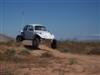
Now for some specs and pictures of the Atomic Baja Bug.
Atomic Baja Bug because I am now located in the atomic city of Los Alamos, NM far away from the bulk of the off-road racing scene.
Target weight 2000 lb
Wheelbase 112
Track width 66
Tire size 33x9.5 or 33x10.5 all the way around
Front Suspension Short Long Arm with 10x2.5 17-19 travel (strapped) (Depends on what I end up with on the rear)
Rear Suspension Trailing Arm with 14x2.5 coilover, 17-19 travel (Strapped), (Depends on exact angle of the CVs)
Driveline 091 Bus with 930 CVs
Engine Undecided but leaning toward a very traditional 1835 Type 1 with a single Weber 40 putting out around 100-120 hp
Steering 1.5:1 manual rack & pinion with a Charlynn setup
Front Brakes/Spindles Toyota 4x4
Rear Brakes/Hubs ½ ton Chevy 4x4 modified to accept 930 CV joint
Tubing sizes
2x4x0.120
2x2x0.120 sq
1.5x1.5x0.120 sq
1.25x0.120 rnd
1x0.120 rnd
1x0.063 rnd
|
|
| Back to top |
|
 |
rterfert
Samba Member

Joined: October 08, 2003
Posts: 1419
Location: Yuma Arizona
|
| Posted: Sun Mar 04, 2007 7:42 pm Post subject: |
|
|
Nice start....Better rethink the spare tire location...Might be a little tough to get out in that location (as pictured)
Nice Job so far.
|
|
| Back to top |
|
|
Skidmark
Samba Member
Joined: June 17, 2005
Posts: 2988
Location: Minden, NV
|
|
| Back to top |
|
|
Adrenaline Junky
Samba Member
Joined: April 11, 2006
Posts: 274
Location: Roseville, CA
|
| Posted: Sun Mar 04, 2007 9:20 pm Post subject: |
|
|
| I picked up a couple things in your write up. Thanks. Keep up the good work! |
|
| Back to top |
|
|
runslikeapenguin
Samba Member

Joined: August 07, 2005
Posts: 4674
Location: Federal way WA
|
| Posted: Sun Mar 04, 2007 10:21 pm Post subject: |
|
|
excellent topic. im glad you posted this.
im following everything that you said except for two things.
1. i just leveled the pan im using
2.i dont have a copy of the score rule book
but other than that it seems like im on the right track
_________________
never forget 1-31-07 |
|
| Back to top |
|
|
72BajaBen
Samba Member

Joined: July 30, 2006
Posts: 888
Location: Tampa Florida
|
| Posted: Mon Mar 05, 2007 12:27 am Post subject: |
|
|
| wow it doesnt look like your screwing around with this one. nice job. |
|
| Back to top |
|
|
subybaja
Samba Member

Joined: July 06, 2005
Posts: 1026
Location: Anchorage
|
| Posted: Mon Mar 05, 2007 1:33 am Post subject: |
|
|
Funny, I just saw a similar 4x4 build in Petersen's 4Wheel mag.
-FunBuggy Build
What brought this to mind are your bulkhead lightening holes. They used something similar with a dimpling die, and the result was many times more rigid. Shouldn't be necessary on yours, the sheet being just a web, right?
That's one bulletproof car you're building! Nice.
_________________
Insanity: /ɪnˈsænɪti/ -noun: repeatedly voting for the same party and expecting different results.
Vote Libertarian |
|
| Back to top |
|
|
STEVE0WE
Samba Member

Joined: June 08, 2004
Posts: 167
Location: SAN ANTONIO
|
| Posted: Mon Mar 05, 2007 6:35 am Post subject: |
|
|
Great job on the planning and CAD work. I do have a question/ concern as far a s the front hoop goes.
I see that you built a short front hoop that mirrors the dash, and then added a taller hoop that welds to it. Maybe I am wrong., wont be the first time, but in a front roll over, it seems to me that you are protecting the drivers head with the strenth of a hopefully good weld, verse the strength of a piece of tubing. I can invision that tube sheering the weld on a front rollover, drivers or passengers side impact would collape the "A" piller into the drivers compartment. I understand that its a play car, but I have rolled a few play cars in my time.
Your thoughts?> keep posting pics, its going to be a great build! |
|
| Back to top |
|
|
thrown_hammer
Samba Member

Joined: September 07, 2004
Posts: 790
Location: Indiana
|
| Posted: Mon Mar 05, 2007 10:15 am Post subject: |
|
|
Uber Cool! It does look like the Spare will be difficult to get out.
_________________
1974 Superbeetle Bright Orange
Keeper of the Titanium Monkey |
|
| Back to top |
|
|
jemorgan111
Samba Member
Joined: March 04, 2007
Posts: 25
Location: Los Alamos, NM
|
| Posted: Mon Mar 05, 2007 1:36 pm Post subject: Atomic Baja Bug Build |
|
|
Thanks for all the comments. I should state that the CAD model was made before I got the shell, so I was guessing a little on some of the dimensions. The model also got too big for my computer and I got frustrated trying to make changes to it so I quit working on it. It served its purpose and I will be revisiting the model for more detailed suspension work. The reason I located the spare above the transaxle was to keep the CG of the car as low and centralized as possible. Hanging 80 lbs off the rear bumper or on top of the roof is a pretty bad compromise. I am pretty sure I can access through the rear window opening. I have seen several 5-1600 cars get a spare in there. It will not be the most expedient tire changing operation and I might do it different if it were a race car but I will mock it up and try it. It may or may not work out.
I didn't dimple die the plate because it is 1/8" thick and the last time I dimpled 1/8" it got warped and was trashing my dies. The dimpling increases the strength as you have shown in the pictures but where I have located the piece it is loaded vertically. Think of the vertical section on a I beam with the 2x2 as the bottom web and the 1" round as the top web. Best way I can describe it.
Response to the double front hoop. I wanted this car to be different and this was one area I found the fit to work well with a non-traditional structure. The rear shock mount is very different from the "standard" setup on many cars also. If I do my job right with a full penetration weld and the appropriate gusseting it will be stronger than the tube around it. If it breaks the crash was so severe it wouldn't matter because I would be dead anyway. Many race buggies terminate the "roll bar" at the window plane, go to the skunz section of race-dezert.com and check out the cars, or go to desertrides.com and they have similar featured vehicles including Robby Gordon's TT.
Thought of another major issue I missed in the 10 tips, so here is number 11.
11. Always make a complete weld on any joint. Never leave a joint with an un-welded portion. The end of the weld acts as a stress riser and will cause the joint to fail in the event it gets loaded high enough from a roll over, bottom out, whatever. The Atomic baja shell will come off, more diagonals and the required 3x3 corner gussets or equivalent will be added to the cage and then when everything will be fully welded and painted the body will be dropped back on the frame. Obviously this method will not work on a car with all the sheet metal intact. A friend with a drag Mustang showed me a very cool trick he did to achieve full circumference welds in a car he did not want to cut the top on. He cut holes in the floor at the exact locations the cage with a hole saw and lowered the cage down a couple feet so he could weld the tops of the tubing then he lifted the cage back up and slid 4x4 plates under the base of the cage and bolted the plates down to the body with matching backer plates, then he welded the plates to the cage. The holes are covered from the outside, the inside and the cage passed NHRA specs.
Post this message text and/or pictures anywhere people find it useful. My only request is that you acknowledge me as the author. I am thinking about posting it on the Race-dezert.com forum because that site has a lot of fabrication going on too.
Thanks for all your comments
Look for a post on tube notching correctly without a $2000 piece of milling equipment soon. |
|
| Back to top |
|
|
runslikeapenguin
Samba Member
Joined: August 07, 2005
Posts: 4674
Location: Federal way WA
|
| Posted: Mon Mar 05, 2007 2:40 pm Post subject: |
|
|
i dont know dude, that looks like pretty bad sheer to me.
_________________
never forget 1-31-07 |
|
| Back to top |
|
|
el loco kingo
Samba Member

Joined: October 02, 2005
Posts: 607
Location: temecula, california
|
|
| Back to top |
|
|
takotruckin
SUPER Baja

Joined: August 14, 2005
Posts: 2378
Location: stuck in fresno, ca
|
| Posted: Tue Mar 06, 2007 7:35 pm Post subject: |
|
|
man, this really makes me want to cut my car up and start over. i will have a full tube frame car very soon (evil laugh here)
now just how do you plan on making this thing under 2000 lbs? my car is a full pan baja, with a much heavier motor, but WAY less steel and it weighs a tad over 2400.
_________________
Member of the baja's that don't run club, for now!! |
|
| Back to top |
|
|
STEVE0WE
Samba Member
Joined: June 08, 2004
Posts: 167
Location: SAN ANTONIO
|
| Posted: Tue Mar 06, 2007 8:21 pm Post subject: |
|
|
| Im looking forward to seeing that baby on the scales also. After finishing the manx, and the prostock, 2000 lbs. without using chromoly is going to be impressive. I went well over that with the manx, but the body weighs quite a bit. |
|
| Back to top |
|
|
baja5
Samba Member
Joined: February 28, 2004
Posts: 4326
Location: Ramona,Ca.
|
| Posted: Tue Mar 06, 2007 8:28 pm Post subject: |
|
|
| Mine's 2280 with me in it. |
|
| Back to top |
|
|
jemorgan111
Samba Member
Joined: March 04, 2007
Posts: 25
Location: Los Alamos, NM
|
| Posted: Tue Mar 06, 2007 8:52 pm Post subject: Atomic Baja Bug Build |
|
|
Its good to see others real weights coming in a little over 2000 lb. The 2000 lb estimate is a combination of the parts I have on hand weighed on a bathroom scale and the computer generated stuff for the steel on the chassis. I am only running a front windshield so that should save a fair amount. I would say the 2000 is optimistic based on everone's feedback so call it 2000 up to 2500 no people but full of gas. One pretty big guess was the motor, I used a number I found on the web because I didn't have a motor to weight.
I am probobly going to get a set of scales before I order springs so that I get them right the first try. If anyone has anything similar and has the spring weights they used I would love to know so I get in the ballpark. I plan on using the individual weights and do some calculations to start with.
I am also doing some FEA analysis on the front roll bar based on some comments about the design. The initial work I have done is inconclusive so I need to redo it with more detail of the joint. I will post it when completed, it should be very interesting. I would love to FEA the entire chassis but my computer is not up to that task and it would take some time to set that one up right.
I will also post a side view line drawing with the dimension points I used as a starting point to cut and bend the tubing if anyone wants to make their own chassis. |
|
| Back to top |
|
|
DONT
Samba Member
Joined: October 19, 2006
Posts: 338
Location: Gilbert, AZ
|
| Posted: Wed Mar 07, 2007 9:11 am Post subject: |
|
|
Now that you got everybody all hot and bothered, you got to keep it up!! 
Can't wait to see more. Since Baja5's car is about 2100 empty and is not skimping on any tubing, you may not be far off. Since it looks like you are deep into the tech of it, I imagine we will see some carbon fibre in this before it is done. |
|
| Back to top |
|
|
jemorgan111
Samba Member
Joined: March 04, 2007
Posts: 25
Location: Los Alamos, NM
|
| Posted: Wed Mar 07, 2007 9:26 pm Post subject: FEA on the Atomic Baja Bug vs Standard Front Roll Hoop |
|
|
Well I got a pretty good finite element analysis model build for the front hoop on the car and a pretty standard configuration to compare it against. Finite element analysis is the only real way to analyse the stress and strain in the structure. The configuration on my car eeked out a slight strength advantage over a standard configuration. I remind you that it is not finished and what I show in the FEA is a rough approximation of the final product. What I weld into the car will look a little more elegant than what I drew up on the computer.
Von Mises stress of the standard configuration (1.4E8 N/m^2 through the joint)
Von Mises stress of my configuration (6.7E7 N/m^2 through the joint)
Both have a fairly even stress disturbution with no glaring stress concentrations.
Load was assumed to come straight down from the front hoop. |
|
| Back to top |
|
|
STEVE0WE
Samba Member
Joined: June 08, 2004
Posts: 167
Location: SAN ANTONIO
|
| Posted: Thu Mar 08, 2007 6:34 am Post subject: |
|
|
Well fella, you have a fine set of finite element analysis on ya! If you start seeing bumps, see a doctor! I dont know much about computer modeling, so I am asking out of 100% rocks in head. I see plate bracing in both models, but I dont see it in the car? Can you run the same analysis without the bracing? most of the guys I see dont run in triangle bracing when they put in a class 11 kit, and that would effect the results greatly. Can you change that and re-post?
Thats a really cool program.
I really like the side view of the door section. I think that it follows the lines of the car nicely. Might have to take a look at that idea for my next project. Is that power steering I see? If it is, very nice. I will be upgrading that soon.
How are you going to mount the rear swing arms? Did you weld in a threaded bung into the box tubing like on a stock VW? |
|
| Back to top |
|
|
Durf
Samba Member

Joined: October 19, 2006
Posts: 245
Location: San Diego
|
| Posted: Thu Mar 08, 2007 12:19 pm Post subject: Re: FEA on the Atomic Baja Bug vs Standard Front Roll Hoop |
|
|
| Quote: |
| Load was assumed to come straight down from the front hoop. |
What if the load isn't coming straight down? Say from left to right or front to back. |
|
| Back to top |
|
|
|


