| Author |
Message |
Ted2
Samba Member
Joined: April 07, 2004
Posts: 247

|
 Posted: Fri Feb 17, 2023 3:29 pm Post subject: Re: Zarwerks shop spy cam .... Posted: Fri Feb 17, 2023 3:29 pm Post subject: Re: Zarwerks shop spy cam .... |
 |
|
| Thanks for the encouragement John. |
|
| Back to top |
|
 |
Iluvmy23
Samba Member
Joined: September 21, 2005
Posts: 31
|
| Posted: Sat Feb 18, 2023 4:49 pm Post subject: Re: Zarwerks shop spy cam .... |
|
|
| Hi John, is your address to send the JK too still 161, etc. |
|
| Back to top |
|
|
johnshenry 
Samba Member
Joined: September 21, 2001
Posts: 9372
Location: Northwood, NH USA
|
| Posted: Sun Feb 19, 2023 8:17 am Post subject: Re: Zarwerks shop spy cam .... |
|
|
| Iluvmy23 wrote: |
| Hi John, is your address to send the JK too still 161, etc. |
PM sent.
_________________
John Henry
'57 Deluxe
'56 Single Cab |
|
| Back to top |
|
|
sunroof
Samba Member

Joined: October 06, 2006
Posts: 1791
Location: Winnipeg
|
| Posted: Sun Feb 19, 2023 11:54 am Post subject: Re: Zarwerks shop spy cam .... |
|
|
I look forward to it.
As an aside: When I was restoring the engine in my '54 the heater boxes were beat to shit, apparently the previous owner went off road a lot. I managed to get them apart, pound them out and get the mechanism all working. A very satisfying job.
Don
_________________
Better and better mistakes! |
|
| Back to top |
|
|
johnshenry
Samba Member
Joined: September 21, 2001
Posts: 9372
Location: Northwood, NH USA
|
| Posted: Wed Mar 01, 2023 5:25 pm Post subject: Re: Zarwerks shop spy cam .... |
|
|
Some work last few days on some speedo pods. Split speedo pods with damaged or missing ignition switch caps are a dime a dozen. Sam Steel in Spain makes a repro, but it is a resin cast, not true bakelite and cannot stand up to the heat of soldering the brass bus bar on. So having and being able to use an original ignition switch cap is a big deal.
This one had cracked away part of one of the bosses that one of the three screws went through. It was still functional with 2 screws, but it would not have been long before, with use, the others would crack off.
I have used this type of "tape mold" JB Weld repair before for other things. First it is important to clean all surfaces with solvent well. It is a bit of a trick to get the epoxy to settle in an completely fill the void (coffee stirrers and toothpicks are used). Q Tips and solvent used for cleanup before letting it cure. Once cured, it is shaped a bit with a file and drilled out. Since the epoxy "fill" was much taller than the other bosses as the missing piece was so large, I used a longer M3 machine screw to hold it there. The head of the screw has to be turned down a bit first to get it to fit inside the narrow slot in the housing.
_________________
John Henry
'57 Deluxe
'56 Single Cab |
|
| Back to top |
|
|
johnshenry
Samba Member
Joined: September 21, 2001
Posts: 9372
Location: Northwood, NH USA
|
| Posted: Tue Jun 20, 2023 7:07 pm Post subject: Re: Zarwerks shop spy cam .... |
|
|
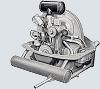
Been doing a lot of jacketed K manifold restorations lately. Have been doing these for probably 20 or more years now. And like everything else that we do repetitively, we find new, and more efficient ways to do them. I have a very old series of pics over at my site zarwerks.com, but thought to do an updated, and far more detailed series here on my "spy" thread. That, and I wonder how long I will keep doing this... and how to transfer the knowledge should someone want to take this up.
This series will take several phases and, to be sure, it still won't impart everything someone would need to know to do this. There is a lot of trial and error/tweaking that goes on to fab these new legs. But it should provide a good mid level detail of the process that I use.
The "jacketed K" intake manifold came out in March 1950 and lasted until late '51 to early '52 in my opinion. The actual end date is not documented. Like the intakes before, and after it, it suffered from the same design flaw; too thin steel tubing on the heat riser tubing. Repeated heat cycling accelerated rusting of the tubing resulting in rust perforation and ultimately egress of exhaust gases into the engine bay where they could/would be sucked into the cabin heating system. This tubing is 18mm on the outside diameter, and 1mm thick in the walls. The heatriser path on the intake is not via a single piece of tubing through the aluminum jacket, but via two separate heat riser "legs" on the right and left side with a cavity in the aluminum jacket to allow heated exhaust gas to flow right to left in the engine bay and warm the intake runner and carb riser. As the gas moves right to left through the heat riser tubing on the intake, the right side heat riser is hotter and usually deteriorated before the left side riser. In the restorations that I do on these intakes, I always replace the heat riser on both sides.
The first phase will show the tools I use and how to assess an intake before proceeding. Its gotten a bit late tonight so I will just post this for now, pics and other details in the coming days..
_________________
John Henry
'57 Deluxe
'56 Single Cab |
|
| Back to top |
|
|
johnshenry
Samba Member
Joined: September 21, 2001
Posts: 9372
Location: Northwood, NH USA
|
| Posted: Wed Jun 21, 2023 7:24 pm Post subject: Re: Zarwerks shop spy cam .... |
|
|
So that fixture/plate (above) is 1/8" aluminum with holes and drillings to mirror the head and heat riser locations on a 25hp engine. Original 6mm "panel press nuts" but they kept falling out after a few years of use so some JB weld added to help hold them in. Originally it didn't have the angle iron frame. But back when I was making repro non-jacketed Ks and doing that long weld between the heat riser and intake runner tubing, the heat would cause the intake, and the fixture panel to warp/twist. So I made the angle iron frame to stiffen it.
The other main tool, a Harbor Freight 2 Ton pipe bender. The 10mm "shoe" works best with this size tubing.
Materials? Tubing is sourced from McMaster Carr in 6 foot lengths. Not cheap, but ideal for these fabrications. 18mm OD, 2mm thick in the walls, so rust out will not ever be a problem.
Flanges: I had a CAD drawing made and I have them Laser Cut. Off the top of my head, I don't recall the name of the shop in the midwest that does them. Lots of shops do this. I think they run about $3 a piece if I have 100 or more made at a time. 1/4" thick. In the pic above, you can see the flanges, and a set of "blanks" cut from the tubing. Left side blank 12.5" right side is 15"
Other tool not shown, I have a 12" carbide disc metal chop saw from HF. It works great cutting this tubing. Rest of the tools are normal shop stuff, with a few custom metal pieces made, read on. And of course, a MIG welder.
So a first phase is "assessment". This example intake, as I received it from a customer, is fairly common. Some previous repair attempts on this one to make the heat risers intact. Most often I get them with thoroughly rotten heat risers, or they are missing all together.
A quick test fit on the jig found this one badly bent on one end. Off on the head location by a good 3/4" or so. This intake runner tubing is quite thin and bends easily. Often, if they are off by just a bit, I just manhandle them to make them fit. One method is to just step on one end and pull, or push the other to make them line up on the fixture (see pic below). But on this one, the bend was clearly on one side only. So I opted to clamp it in the vice and "open" that bend up a bit. It took very little muscle to feel it "give" and on first try, back on the jig, it aligned perfectly.
The other check is to eyeball the intake runner endcastings end to end to make sure the intake isn't twisted. Very few are. Problem is the intake manifold made a convenient "handle" for people moving/storing engines and they often get tweaked. So some up front inspection and tweaking is sometimes needed to get these things straight again before moving forward with re-legging them.
Pics below show what I have described.
_________________
John Henry
'57 Deluxe
'56 Single Cab |
|
| Back to top |
|
|
johnshenry
Samba Member
Joined: September 21, 2001
Posts: 9372
Location: Northwood, NH USA
|
| Posted: Thu Jun 22, 2023 7:13 pm Post subject: Re: Zarwerks shop spy cam .... |
|
|
Ok, let's get started. Next phase is "extraction". This is the removal of the original steel heat riser tubing inside the aluminum jacket. This job varies greatly depending on the condition of the intake, previous "repair" attempts, etc. I used to use all kind of hammer and chisel techniques, even made some custom pneumatic air chisel bits to peel back the old steel tubing. But more recently, developed a Dremel tool "arthroscopic" technique using some special bits that works quite well.
Cutting this intakes heat riser tubes back to withing a half inch or so of the jacket, it is clear that a previous attempt was made to repair a compromised/rusted heat riser. In this case, a "slip" tube was inserted inside the tubing and a new section of tubing used over that. In this case, the internal tube section was easily removed. On the other side, same thing.
So the arthroscopic technique involves 2 steps. The first is to use an inverted cove bit on the Dremel (these bits are found at McMaster Carr and are very sharp and work very well) to cut a circumferential line inside the aluminum jacket about 40 mm into the jacket.
The second step is to use a 4" long McMaster Carr "Double Cut" tapered deburr bit on the dremel to cut two longitudinal cuts through the steel tubing, from the circumferential cut to the outer edge of the opening. One on the bottom, and one on the top of the aluminum jacket bore. By sound, it is pretty easy to hear when the bit in the Dremel has cut through the steel tubing and is into the aluminum. Now in this example shown here, the steel was very thin, and the cut pieces came out of the jacket VERY easily. This is not the typical case. More often, the steel tubing wall is thicker and doing the cutting and extraction is more of a chore. In this case, once the cuts were made, the tubing sections could be removed by quickly "collapsing" the tubing section and pulling it from the jacket.
Again, this intake was unusually easy. There are no bonding properties between the steel tubing and the aluminum jacket, so once the steel is collapsed and pulled away from the aluminum, it is removed easily. More often the heat riser tubing is thicker and getting thorough, complete cuts with the Dremel bits is harder, as is collapsing the steel tubing and pulling it out of the jacket.
Next phase, we'll ream out the jacket and start to fab the new legs. Stay tuned!
_________________
John Henry
'57 Deluxe
'56 Single Cab |
|
| Back to top |
|
|
Grant Reiling
Samba Slow-Change Artist
Joined: November 28, 2003
Posts: 492
Location: behind the wheel
|
| Posted: Fri Jun 23, 2023 12:47 pm Post subject: Re: Zarwerks shop spy cam .... |
|
|
| johnshenry wrote: |
Ok, let's get started. Next phase is "extraction". This is the removal of the original steel heat riser tubing inside the aluminum jacket. This job varies greatly depending on the condition of the intake, previous "repair" attempts, etc. I used to use all kind of hammer and chisel techniques, even made some custom pneumatic air chisel bits to peel back the old steel tubing. But more recently, developed a Dremel tool "arthroscopic" technique using some special bits that works quite well.
Cutting this intakes heat riser tubes back to withing a half inch or so of the jacket, it is clear that a previous attempt was made to repair a compromised/rusted heat riser. In this case, a "slip" tube was inserted inside the tubing and a new section of tubing used over that. In this case, the internal tube section was easily removed. On the other side, same thing.
Next phase, we'll ream out the jacket and start to fab the new legs. Stay tuned! |
Excellent work (and thanks for sharing pics of your extensive extractive techniques on this procedure).
Hats off to you John 
I'll look forward to future updates; be well 
Grant
_________________
1952 Azure Blue 12G (LHD Deluxe 3-fold sunroof Sedan).
"What you really know is possible in your heart is possible.
We make it possible by our will.
What we imagine in our minds becomes our world. Thats just one of many things I have learned from water."
Misaru Emoto
The Hidden Messages in Water |
|
| Back to top |
|
|
johnshenry
Samba Member
Joined: September 21, 2001
Posts: 9372
Location: Northwood, NH USA
|
| Posted: Mon Jun 26, 2023 7:00 pm Post subject: Re: Zarwerks shop spy cam .... |
|
|
Next up is reaming out the jacket to accept the new tubing/legs.
An 18mm straight flute reamer is used for this, and a beefy Bosch drill.
This is purely an "eyeball" procedure of placing the end of the reamer at the face of the bore, starting the drill slowly and allowing it to follow the existing bore. In some cases, very little material is removed. I leave the aluminum "flashing" at the entrance to the bore intact so the repair looks as original as possible. A quick pass with the shop vac to remove the shavings and a test fit with a section of new tubing.
Years ago I used to sell fabricated legs that people might want to use to do their own repairs, but quickly realized that every intake is different in the exact angle of the tubing bore and there was no way I could guarantee a perfect fit. And this boring "by hand" is why. The angle of the tubing exit is probably a tiny bit different on every intake. As you will see in the details showing the fabrication of the new legs, there is a lot of trial and tweak that goes on to make sure everything is perfectly square with regards to how this part attaches to the engine.
Extraction of the original steel on the other side, and reaming and test fit.
A box of all the legs replaced in the past. I have this weird idea of using them for an artpiece somehow in the future. Sort of like the crutches at the sanctuary of Lourdes....
_________________
John Henry
'57 Deluxe
'56 Single Cab |
|
| Back to top |
|
|
sunroof
Samba Member
Joined: October 06, 2006
Posts: 1791
Location: Winnipeg
|
| Posted: Mon Jun 26, 2023 7:04 pm Post subject: Re: Zarwerks shop spy cam .... |
|
|
Thank you for taking the time to document this process.
Don
_________________
Better and better mistakes! |
|
| Back to top |
|
|
johnshenry
Samba Member
Joined: September 21, 2001
Posts: 9372
Location: Northwood, NH USA
|
| Posted: Sun Jul 02, 2023 6:29 pm Post subject: Re: Zarwerks shop spy cam .... |
|
|
On to fabrication of the new heat riser legs. Each are similar, but the right side one is a bit longer than the the left. "Blank" tubing section are cut from 2 meter long lengths that I get from McMaster Carr, 15" for the right side, 12.5" for the left. As the legs are fabricated, there is some waste as there is a minimum length that you can have from a bend, and later some of the tubing is cut off. More on that below.
Each new leg has two bends. One, just outside of the aluminum jacket is a very slight bend. While I used to try to measure it, I found (and mentioned earlier) that every intake is different and thus, every bend ever so slightly different. I just do the bends "by eye" and also looking at marks I have made on the intake fixture. So I am looking for the bend to match the proper angle marked on the fixture, knowing that later I will cut the end of it short.
Now in this fab, I found that I actually overbent the tubing a bit, and having cut it off with the chop saw already, putting it back in the tubing bender upside down to "unbend" it a bit was not an option. So I have to use some other tooling to do this. In the pics below you can see that I have welded 5 flanges together and can place them in the vice and it gives me a nice tight bore to hold the cut short end of the tubing while I relax the bend a bit. I use a 2+ foot section of pipe and a "dent collar" (more on those below) with the tubing section in the vice. I have to take care not to distort the circular shape of the end of the tubing where it fits into the aluminum jacket or it won't slip in there. And although the tubing is 2mm thick in the walls, it is a soft carbon steel and actually yields in the vice with a moderate tug on the pipe.
Back in the fixture again after some tweaking, and eyeballing the tubing over the hole for the heat riser flange, and I can now see that this one is bent properly and is extending directly over the flange hole in the fixture. With a sharpie marker I make a longitudinal line on the tubing to show the top surface for the next bend, and a lateral mark to show where the tubing crosses the flange opening in the fixture.
In the tubing bender, I orient the tubing section with the marked spot centered on the "shoe" (that is what the curved piece on the bender ram is called). In that pic, you can also see a dent collar between the tubing and the upper roller in the pic. The dent collar is a small piece if tubing cut about 1/3 of the way around and it's purpose is to make sure that the roller doesn't leave a tooling mark/dent in the tubing when it is pressed/bent. The reason there is not a dent collar under the lower roller in the pic is that this location on the tubing will be past the flange when the leg is completed and that portion will be cut off and scrapped.
Again, this just a trial and tweak process. This second bend goes nearly a full 90 degrees. The objective is, when the other end of the tubing is slipped into the aluminum jacket, the flanged end, after the bend, should bend down, and drop right through the center of the flange hole in the fixture.
In this case, it was close, but the bend was a bit "out".
_________________
John Henry
'57 Deluxe
'56 Single Cab |
|
| Back to top |
|
|
johnshenry
Samba Member
Joined: September 21, 2001
Posts: 9372
Location: Northwood, NH USA
|
| Posted: Sun Jul 02, 2023 6:58 pm Post subject: Re: Zarwerks shop spy cam .... |
|
|
Now to fix the bend being a bit "out", I have to bring it in a bit. The tubing section goes back in the bender, but now, the marked bend center is placed a bit farther out from the center of the shoe. Note that the dent collar is used again on the upper roller. After "bring the bend in" a bit, the tubing now drops into the center of the flange hole in the fixture.
But as happens in about half the fab cases, the tubing isn't going through the opening perfectly perpendicular and when slipping a new flange on the tubing, it won't bolt perfectly flat to the fixture surface. And this is critical for a good seal between the intake and the muffler on the engine. So I do something I call "slanting the flange" and use 5/8 round grindstone in the flange bore but at an angle that matches the angle of the bend in the tubing, relative to the bolt up position of the flange. After just a bit of grinding, the flange bolts up to the fixture perfectly flat.
The other thing that I have to pay attention to, is the position of the intake runner endcastings as they are bolted to the fixture. Since the ends of the endcastings tilt up on both ends, it is possible to bolt the intake into the fixture tilted a bit front to back. So checking periodically that the gap under each end of the intake runner endcastings is equal, is important.
Once the tubing is bend correctly, and everything bolts up "flat" to the fixture, the flange is tacked up to the tubing with the MIG welder. As with any welding, "shiny metal" is key, so the surfaces of both the flange and the tubing are ground with a grinding disc before tacking up.
_________________
John Henry
'57 Deluxe
'56 Single Cab |
|
| Back to top |
|
|
bwaz
Samba Member

Joined: August 24, 2004
Posts: 1781
|
| Posted: Mon Jul 17, 2023 10:28 am Post subject: Re: Zarwerks shop spy cam .... |
|
|
| what a great share John. Thanks! |
|
| Back to top |
|
|
johnshenry
Samba Member
Joined: September 21, 2001
Posts: 9372
Location: Northwood, NH USA
|
| Posted: Wed Jul 19, 2023 7:23 pm Post subject: Re: Zarwerks shop spy cam .... |
|
|
So continuing, the same process on the left side. This time it works out much better, the tubing bends are made and no "slanting" of the flange is needed, it bolts up perfectly flat on the fixture with no tweaking. About half of them go this way.
After flanges are tweaked to bolt up flat, and MIG tacked up, the flange is fully welded onto the tubing. The excess tubing under the flange is cut off, then the flange/tubing is ground flat to make the perfect mating surface for the flange to the muffler with a gasket.
The final fabrication steps on these replacement "legs" is to create the bolt head seats on the heat riser flanges. This is done using a bit in the drill press called and End Mill. With a slow turn and some cutting oil, the face of the flange where the bolt head will sit is given a little depression for each bolt location.
Finally, the ends of the heat riser legs that will get epoxied into the aluminum jacket are wire brushed to remove the tubing mill coating, then shallow radial and axial grooves are cut into the to give the epoxy and extra "bite" on the tubing.
Here is a finished heat riser flange end with the bolt seats cut in.
_________________
John Henry
'57 Deluxe
'56 Single Cab |
|
| Back to top |
|
|
johnshenry
Samba Member
Joined: September 21, 2001
Posts: 9372
Location: Northwood, NH USA
|
| Posted: Tue Jul 25, 2023 6:24 pm Post subject: Re: Zarwerks shop spy cam .... |
|
|
And lastly on the Jacketed K resto, the "glue up".
At this point the fabricated legs are ready to be installed. Epoxy is mixed, Q tips and toothpicks available, glue brush and a small amount of lacquer thinner for cleanup.
First, epoxy is applied in a thin coat to the inside of the freshly reamed out jacket bores. It is normal for there to be big voids in these jackets around the heat riser tubing and I try to fill them if they exist. Then, a thin coat on the ends of the new legs. The new legs are "offered up" as the English say, to a loosely bolted down intake. They slip into place and they are each loosely bolted down.
A good bit of excess epoxy oozing out means that the epoxy is uniform around the tubing in the jacket. Then before tightening up everything on the fixture, a final measurement is taken using a measured 70mm block of wood to check the clearance under the jacket. I found out the hard way long ago that it is possible to have the intake tilted on the fixture and thus reducing the clearance under the jacket (to the seam on the engine block).
Then cleanup begins on the epoxy. First dry Q tips are used to sweep away the excess on each side. The Q tips are dipped in lacquer thinner make thing really clean. Toothpicks may be used to scrape away epoxy in between the heat riser and intake runner tubes.
Once cleaned up, the repair is amazingly invisible. Look at the pic below. No "gap" is seen, no epoxy visible anywhere. Looks just like a brand new original where the jacket was likely cast around the tubes with molten aluminum in a cast.
_________________
John Henry
'57 Deluxe
'56 Single Cab |
|
| Back to top |
|
|
obieoberstar
Samba Member

Joined: March 07, 2002
Posts: 1128
Location: Tucson
|
| Posted: Tue Jul 25, 2023 8:28 pm Post subject: Re: Zarwerks shop spy cam .... |
|
|
Thank you for sharing your process. It's the little details. Especially machining the flanges for the fasteners.
Excellent work. |
|
| Back to top |
|
|
johnshenry
Samba Member
Joined: September 21, 2001
Posts: 9372
Location: Northwood, NH USA
|
| Posted: Fri Nov 03, 2023 7:00 pm Post subject: Re: Zarwerks shop spy cam .... |
|
|
Time for some new content: Tapping split speedometer knobs for brass screws and installing them.
Yes, something here bugs me a bit. The knob shafts were originally peened over like rivets on the backsides. Screws were not used. But two things here. One, using screws makes the knobs and the switch contacts serviceable, removable for cleaning, troubleshooting, etc.. An improvement. Second, and I did try to figure this one out, it would be all but impossible to peen ends of NOS knobs (which seem to be in good supply for some reason) while installing them in a pod without cracking them, doing other damage, etc. Impact/hammering of the shaft ends would surely result in damage. Using some kind of press (which is probably what the factory did) would still require some kind of even support of the knob face while the shaft end was pressed. At one point I endeavored to create some kind of knob saddle using a clay or plaster imprint of a knob, but just gave up on it. The brass screw solution is not "vintage correct ideal", I agree, but it is functional and allows for solid pod restorations.
So I will post some pics below, but explain here first.
First is the tooling. The knobs, whether NOS or good originals, need to be drilled and tapped for screws properly. So using a small wooden block, I made a tool that has some 3/16" aluminum plate attached with screws, and a clean 3mm hole drilled to accept the knob shaft. This gives a solid, square fixture to hold the knob for drilling. This black was later modified to accept the larger '48 and earlier knobs. The knob sits into a shallow bore on the backside which holds it and prevents it from spinning. A small piece of custom rubber allows the face of the knob to be pressed flat into the fixture while in the drill press without damaging it.
The drill bit in the drill press is a 2.05mm or #46 bit (sourced from Mcmaster Carr). A little bit of masking tape on the bit shaft shows me how deep I need to drill the shaft.
_________________
John Henry
'57 Deluxe
'56 Single Cab |
|
| Back to top |
|
|
johnshenry
Samba Member
Joined: September 21, 2001
Posts: 9372
Location: Northwood, NH USA
|
| Posted: Fri Nov 03, 2023 7:14 pm Post subject: Re: Zarwerks shop spy cam .... |
|
|
Next, is tapping the knob shaft. The tap is a 2.5mm x .45mm pitch. Now I have in my stubborn, sordid past, chucked this tiny 2.5mm tap into a cordless drill and trusted that the torque limiter set on its lowest setting would protect the tap from hanging and snapping off. But the last time it happened, I gave up on that. I simply put the tap in a tiny pair of vice grips, put a micro drop of oil on the tap threads, apply a little pressure and start turning... by hand.
Once tapped, I blow out the newly tapped bore with compressed air (either a blow gun on a line, or those little "duster" cans of compressed air work well too). There can be a good bit of "swarf" still in there. Then, because of the threadlocker to be used later, I spray some carb cleaner in the bore and blow with air again (carb cleaner will not dissolve the surface of the knobs).
Forgot to mention is earlier. On NOS knobs, I grind down the peenable "rivet" flange to make it flat on the end, then run it on a wire wheel on the grinder. On original knobs where the rivet peen has been drilled away to remove the knob from the pod, I do a light grind to make the end of the shaft square. This is done before drilling/tapping.
_________________
John Henry
'57 Deluxe
'56 Single Cab |
|
| Back to top |
|
|
johnshenry
Samba Member
Joined: September 21, 2001
Posts: 9372
Location: Northwood, NH USA
|
| Posted: Fri Nov 03, 2023 7:28 pm Post subject: Re: Zarwerks shop spy cam .... |
|
|
The screws I use are slotted pan head, brass 2.5mm x .45mm, 5mm in length. I get them at McMaster. Two washers are used. One is a stainless washer with 3mm ID. The other is an M2.5 brass washer ad it does not slip over the shaft of the knob. The stainless washer slips over the knob shaft, and acts as a thrust washer between the screw head and the top of the knob shaft bore in the pod.
I apply some white lithium grease on the knob shaft (not shown) as well as both side of the stainless thrust washer.
Before installing the knob in the pod, I use a toothpick to put some "Red" threadlocker in the newly tapped bore. Then I install the knob. In these pics, I used a trashed pod section that is missing the other screw terms. But it shows the relative position of the screw when installed.
Lastly, when tightening the screw, look closely at the gap on the front of the pod, under the knob. Often, the proper setup is not with the screw tightened all the way down in the shaft. A "business card" gap should exist under the knob backside and the face of the pod. Too tight, and the knob will score the face of the pod when it is used. Tighten the screw just enough to leave a tiny gap underneath the knob in the front. More important, Do not twist, "test" the knob action for around an hour after setting the screw. This allows the threadlocker to set up first. With the thrust washer properly greased, and after the threadlocker set up, the knob shaft and screw should rotate easily in the pod, without "unscrewing".
_________________
John Henry
'57 Deluxe
'56 Single Cab |
|
| Back to top |
|
|
|


