| Author |
Message |
johnshenry
Samba Member
Joined: September 21, 2001
Posts: 9414
Location: Northwood, NH USA

|
 Posted: Sun May 24, 2009 8:17 am Post subject: Posted: Sun May 24, 2009 8:17 am Post subject: |
 |
|
| eurodub wrote: |
hey there John, i have a small question. as you have often dealt with speedo restos and calibration, will there be any significant difference when running 15" wheels on a split speedometer?
from what i could check here the local technical inspection allows up to 3% tolerance when changing wheels/tires. |
I just measured the diameter if the wheels on my '50 (5.25 x 16 "76L" Avon Tourist tires) and got 26.5. Looking in the table above, that would give you 2+ mph difference at the upper end (78mph in a split, yeah, right) over the 5.60 x 15s. Over a 185/65/15, 8 mph. Doing the math, 15 inch bias ply vs 16 in boas ply, it does indeed look like about a 3% difference.
_________________
John Henry
'57 Deluxe
'56 Single Cab |
|
| Back to top |
|
 |
johnshenry
Samba Member
Joined: September 21, 2001
Posts: 9414
Location: Northwood, NH USA
|
| Posted: Sun May 31, 2009 5:51 pm Post subject: |
|
|
Finally, progress and near completion on the interior. I underestimated the work involved in the car once the seats were done, hit a few hard snags, then just avoided the whole project for a long time.
First, I glued up the driver's side B pillar cover before making sure it followed the contour around the panel. Once I realized that, there was no removing it without destroying some headliner under the rear part of the rear quarter, necessitating a new, longer piece.
No problem, I'll just have Lenny send me another one, and the pillows and glove box liners I need too..... so I thought.
Well he did, problem was in the 4 or so years since I got the interior from him, HimmelService changed the manufacture of the cord braun fabric. Cord pattern was identical, color was REAL close, but the weight? Not even close. The new stuff is about half the weight of the old. Lenny says that they said that it was closer to the original, and I think weight wise, they may be right. But the older heavier stuff felt SO much better, like a good sofa and that it would out-wear the rest of the car.
So now what? Since the new B pillar cover (new fabric) would frame the rear quarter panel (old fabric) there was no way. I pleaded with Lenny to scrounge around and try to find even a scrap of the old material I could use. He checked, but had nothing.
So I found loose piece of the old fabric he had sent with the original interior to do the armrests, and it was about twice as much as was needed. I figured I could sew a small piece on the back end of the B pillar cover, and a piece in that same location on the other side, and it would look OK. By matching the cording, you really can hardly see the seam at all.
Then came the interior panels. You might think that would be easy, and all these years with VW, you would have thought I would have known better. The rears were a nightmare, well at least the first one. You cannot see where the clip holes in the body line up against the panel. Unlike the doors, you can't "pull away" the edge and peer in to see if you need to scoot the panel clip up/down, left right. LOTS of cussing there. But before doing the other side, I came up with an easier way...
Anyway, I probably didn't take as many pics as I should of the work, but here is what I have...
I padded underneath the B pillar covers with some "4 ounce" poly batting. I cut a few strips to "ramp up" to the edge that the welting clamp strip made, then covered the whole thing with another layer. I used, pretty much everywhere, 3m "45" spray adhesive. It is a pretty "dry" spray glue that does not soak in. Lenny uses "Camie" glue, which you can order on line, but I already had the 45 so I used that.
No, I didn't put that "dynamat" foil faced stuff in there, the previous restorer did .
Here you can see the extra piece I sewed on to the B pillar covers. Of course I sewed one on backwards and had to cut it away and had to sew it again.
Making the holes for the ashtray screws, a trick I learned way back when I did car stereo installs. The "hot nail" burns through the fabric and the padding.
With an fabric with a polyester content, the fabric is "cauterized" and will not fray. Moreover, it will not "catch" on a drill bit now if you try to drill a pilot hole in the panel below.
The B pillar cover is glued to the panel flange and trimmed. The panel clip holes are burned. You can make out the seam down at the far (left) end.
So to set the panel clips in the proper position on the Driver's side, I cut a template of the panel out of thin posterboard, then "felt" for the flange holes, and used a punch to make holes where they were located. Then I laid the template the back of the panel and marked where they were. This allowed me to orient the clips in the positions that lined up with the holes. It worked perfectly.
The proper positions were not directly toward the panel edge.
I bought some of the early "scissor" type clips from Wolfsburg West. But in some holes they had to get real close to the panel edge and the tab on the backside created a visible "lump" under the upholstery. So I used the Dremel to cut the tab shorter.
Another trick/lesson learned the hard way. Since the door panels have to be bowed and slipped down onto the vertical support the opportunity to have the upper panel clips scratch the door paint is there. I put a layer of masking tape, then 2 layers of duct tape over that. Masking tape adhesive is a little gentler and tends to not leave as much residue when pulled off.
See my point? THat would have been scratched paint for sure.
Problems with the holes in the front panels. The clip holes were all over the place. They varied in distance from the edge from 1/2" to 1". At first I though maybe the holes in the door steel weren't linear, but they are. I'll let Lenny know about that. No easy task to enlarge the holes without damaging the upholstery just underneath. Put I have one of those depth gauge collars for the Dremel that worked well. If you use a Dremel like this, make sure the bit in cinched down tight in the collet, or it can "walk out" and do serious damage. No, didn't happen this time, but I have had problems like that in the past. So I had to modify about a third of the holes to allow the clip to be placed closer to the edge.
I decided to re-use the "U" armrest on the drivers side, and used some closed cell foam for the insert part. I cut a pattern, and sprayed "45" glue, then formed the fabric around the foam.
So I'm not calling it done yet, I still have to do glove boxes, and modify the pillows. And I am waiting on the pop out window seal from Splitparts Unlimited, I should have them this week (right Ricardo??  ). But I did take the split out for a spin tonight, and the seats are real comfy. Was great to drive it again. And I already got a grease stain on them. When putting the seats in, after greasing the rails a bit, check your hands AND your elbows before handling the seats!! ). But I did take the split out for a spin tonight, and the seats are real comfy. Was great to drive it again. And I already got a grease stain on them. When putting the seats in, after greasing the rails a bit, check your hands AND your elbows before handling the seats!!
{Large pics, click on them for bigger view...}
[/b]
_________________
John Henry
'57 Deluxe
'56 Single Cab
Last edited by johnshenry on Mon Jun 22, 2009 9:52 am; edited 3 times in total |
|
| Back to top |
|
|
johnshenry
Samba Member
Joined: September 21, 2001
Posts: 9414
Location: Northwood, NH USA
|
| Posted: Sat Jun 06, 2009 9:07 pm Post subject: |
|
|
Here's some fun from tonight in the shop. There was a thread about sem restoration, coil windings a while back and someone asked if coils could rewound. I did one tonight. Normally I would never think to do this (good used coils, even SHO ones, aren't that hard to find), but I am restoring a set of sems for someone who really wants them as original as possible, and I couldn't resist the challenge.
I used my speedo calibration setup board and turned it around and screwed it to the workbench. I gently tapered a 1/4" dowel and put several layers of heatshrink over it, and it wedge fit inside the bore of the coil core. The copper wire I found at McMaster in the same gauge as the original (the original wire was badly cooked, enamel all burnt off of it), about $25 for enough wire to make about 15 coils (58 feet of wire in a coil in case anyone is interested).
With one hand I could feather the trigger on the drill, and the other guide the wire on the spool with the proper tension, and "walk" it across the rows.
My first attempt:
I spun the drill backwards and unwound the wire, and trashed it. Second attempt was a bit better, but the dowel broke right when I was on the last layer. Third attempt it came out OK. I tested it and it pulls the same 6 amps as the original.
_________________
John Henry
'57 Deluxe
'56 Single Cab |
|
| Back to top |
|
|
johnshenry
Samba Member
Joined: September 21, 2001
Posts: 9414
Location: Northwood, NH USA
|
| Posted: Sat Jun 13, 2009 9:10 pm Post subject: |
|
|
It lives!! The old college porch couch interior ( the pass door panel anyway) is now on the wall at Stan's Classic service in Natick, MA! Complete with ribbed door handles and armrest. Ok, underneath its a block of wood, but the fabric is glued on to it!!
_________________
John Henry
'57 Deluxe
'56 Single Cab |
|
| Back to top |
|
|
johnshenry
Samba Member
Joined: September 21, 2001
Posts: 9414
Location: Northwood, NH USA
|
| Posted: Fri Jun 19, 2009 8:27 pm Post subject: The "Zwitter" Semaphore |
|
|
For years people have asked me if the more common and less expensive smooth sems can be "converted" to ribbed ones, or smooth SHOs to grooved. I tried to do a conversion of an SWF years back and never finished it, I concluded it would never be worth it.
But the other night I noticed that the bolt and rivet hole spacing on the ribbed SWFs and grooved and smooth SHOs were the same. And it appeared as though using ribbed arms, lenses and bulbholders on a smooth SHO ribbed body, mechanism and pivot arm might be pretty easy.
It really was. Most of the work was some Dremel work on the lens, to "deepen" the bolt bosses so the pivot could sit down farther and allow the needed room for the brass bulbholder and ribbed arm. A tiny bit of notching needed to be done to the pivot as well. But in the end, I made a very nice looking ribbed SWF/SHO "zwitter" (neither nor) semaphore.
The ribbed arms, lenses and bulbholders are all available as repros, most are sold in the classifieds. I have been paying $150-$400 EACH for rebuildable SWF Ribbed sems, and I seem to see smooth ones for sale a lot in the $300-$400 range for a pair. The SHOs are bit less common however.
Aside from the logo, the easiest way to spot the SHO sems (grooved or smooth) is that that little spring loaded tab as shown by the red arrow in the pic.
I'll try to post some detail pics of the conversion as I do the other sem of the pair in the next day or two.
_________________
John Henry
'57 Deluxe
'56 Single Cab |
|
| Back to top |
|
|
johnshenry
Samba Member
Joined: September 21, 2001
Posts: 9414
Location: Northwood, NH USA
|
| Posted: Sun Jun 21, 2009 2:14 pm Post subject: |
|
|
As promised, here's some pictures of the modifications. Not the least bit surprising, some one e-mailed me and told me that they had done this mod in the past.... it really is pretty simple. Others asking if I could do some more, or modify sems they already have. The pair shown sold very quickly for about $300 less than I usually sell L numbered SWF ribbed sems for.
As stated above, most all of the work in the modifying of the lens as you can see below:
The screw bosses are cut down and channels deepened on either side. The left side channels are extra deep to allow for passage of the wire. I had previously restored the SHO body and mechanism.
The parts needed, arm, lens, bulb holders and bulb. Not shown are the M3.5 screws. I get these at McMaster in stainless steel cheese head screws. Original screws were plated brass and a tall button head. If I want to be more correct I spin the screws in the drill press, and use a file to re-shape the heads. Then smooth with a scotch brite pad, then run on the buffer. You can see them below.
The modification to the lens allows the pivot arm to sit deep in the lens, with about 1.5mm of clearance for the long brass bulbholder and arm. The screw in the second pic is just there to hold tings together for the picture.
The finished sems. To be even more correct (and "cheat" a bit more), the coil could be wrapped in red cloth tape and an SWF label applied.
_________________
John Henry
'57 Deluxe
'56 Single Cab |
|
| Back to top |
|
|
johnshenry
Samba Member
Joined: September 21, 2001
Posts: 9414
Location: Northwood, NH USA
|
| Posted: Sun Jan 10, 2010 5:55 pm Post subject: |
|
|
Here's some work on a '46 dash pod that was in very, very bad shape. If it weren't for the historical significance of this car (it had been in a flood), this probably wouldn't even have been worth the effort to restore it. I'd also mention that my Zarwerks partner Jim Bremer is the real master of pod resto, but had declined this one. Since I had done a lot of electrical related work for this customer, I decided to take it on. I thought some of the repair tricks here might be useful to others trying to repair broken pods.
As you can see, it is missing the brass bus bar, and the headlight switch terminals (lower left) and 3 of the 4 indicator light "towers" are broken off.
After some glass bead, things are cleaned up a bit
A bus bar is hand made out of some brass stock using shears and various Dremel bits. Jim loaned me an original one as a pattern. Lots of cutting, grinding and test fitting.. no way out of that.
Once shaped, the bar is glass beaded to give it that dull sheen like the original. Two terminal blocks are scavenged from a donor pod. They are drilled out form the switch contact side, and their bases ground flat. The base is drilled (opposite the screw terminal bore) and tapped for a 4-40 brass, bevel head screw seen in this pic.
A second "bridge" piece is shaped to connect the two lower headlight switch terminals together. It is unclear why VW didn't make a single bus bar out of the two for this purpose. There is a clear offset in the bakelite underneath these brass pieces, you can see it in the pic above after glass beading.
The terminals are fixed using the 4-40 screws from the switch contact side. The screw are actually shortened a bit so that they only protrude into the wire hole on the other side by about .5mm once tightened. Then, using a small pointed punch, the eds of the screws are peened open a bit (mushroomed) so that they can't back out (sorry, no pic).
Here both blocks are in place and solder is used to insure continuity between the brass parts. Original pods were soldered in this way also (at least the few originals that I have available for reference). If you really know these pod details, you will notice I did forget to put the starter button lead eyelet under the left terminal. I drilled out the screw head and re-worked that side with the eyelet. You can just make out the end of the 4-40 screw on the right side terminal block.
The heads of the screws in are ground with a small cone bit to create the dish contacts like the originals have.
Here is a technique to re-fasten the indicator bulb contacts that I tested on the donor pod first (you can see the light towers have been cut off), The rivet has been drilled out and the eyelet and contact removed. The bore has been drilled using a 5/32" bit, and small section of 5/32" brass tubing is seen resting on the pod.
The bore in the pod is first tinned with solder, as is the end of the brass tube, and then it is inserted into the bore, and pressed with the soldering iron. Once hot, it slips in and is soldered firmly in place. Bakelite can actually stand a fair amount of heat. If this were PVC or resin, you'd have no chance of doing this.
Sorry for the bad pic, but after slipping the bulb contact and the eyelet on the tube, the end of the tube it flared with a small cone punch, then flattened with another punch. When doing this, make sure the face of the pod is on a smooth, firm and clean surface so you don't mar or crack it.
Here a dowel is used to center the donor section on one of the light towers prior to clamping. Getting the faces ground flat and square and the overall height correct was a matter of trial and error. And trial and error and trial and error and trial and error and ......
Here is the pod almost done. New cloth covered lead wires have been soldered to the eyelets. You can see the repaired light towers and brass bus bar in place.
_________________
John Henry
'57 Deluxe
'56 Single Cab |
|
| Back to top |
|
|
Spanish Flea
Samba Member

Joined: November 20, 2006
Posts: 1244
Location: No. Flo.
|
| Posted: Mon Jan 11, 2010 12:37 pm Post subject: |
|
|
Great work there John!!
Would it be possible to scan the pattern for the Bus Bar.
Mine is broken and soldered back together 
Spanish Flea
_________________
Alte Schule
"Mr. Ford, i don't think what we are being offered here is worth a damn!" - Ernest Breech (On buying VW, March 1948) |
|
| Back to top |
|
|
johnshenry
Samba Member
Joined: September 21, 2001
Posts: 9414
Location: Northwood, NH USA
|
| Posted: Mon Jan 11, 2010 12:52 pm Post subject: |
|
|
| Spanish Flea wrote: |
Great work there John!!
Would it be possible to scan the pattern for the Bus Bar.
Mine is broken and soldered back together
Spanish Flea |
Yeah, good idea. I'll scan the original bus bar, take some measurements and post here. They are very often broken or missing on old pods. Kind of silly overkill too, as the current is only for the ignition and ignition switched circuits, you could much more easily accomplish the same thing with a piece of nominal gauge wire.
But it is one of those "split details" we all know and love....
_________________
John Henry
'57 Deluxe
'56 Single Cab |
|
| Back to top |
|
|
bwaz
Samba Member

Joined: August 24, 2004
Posts: 1815
|
| Posted: Mon Jan 11, 2010 1:58 pm Post subject: |
|
|
Just to step back a posting or two, would the screws inside the ribs of the semaphores be normally unpainted, or the same color as the car?
thanks
Brian |
|
| Back to top |
|
|
johnshenry
Samba Member
Joined: September 21, 2001
Posts: 9414
Location: Northwood, NH USA
|
| Posted: Mon Jan 11, 2010 3:31 pm Post subject: |
|
|
| bwaz wrote: |
Just to step back a posting or two, would the screws inside the ribs of the semaphores be normally unpainted, or the same color as the car?
thanks
Brian |
On cars that had them painted body color, the screw heads are painted in my experience. There are several period pics showing body color painted sems, but most I have seen are black and the screws usually aren't painted. I had a box of NOS SWF sems a few years back and the (black) arms had unpainted screws.
_________________
John Henry
'57 Deluxe
'56 Single Cab |
|
| Back to top |
|
|
beetleseb
Samba Member
Joined: November 09, 2006
Posts: 430
Location: Cheltenham UK
|
| Posted: Thu Jan 21, 2010 1:40 am Post subject: |
|
|
| johnshenry wrote: |
Here's some fun from tonight in the shop. There was a thread about sem restoration, coil windings a while back and someone asked if coils could rewound. I did one tonight. Normally I would never think to do this (good used coils, even SHO ones, aren't that hard to find), but I am restoring a set of sems for someone who really wants them as original as possible, and I couldn't resist the challenge.
I used my speedo calibration setup board and turned it around and screwed it to the workbench. I gently tapered a 1/4" dowel and put several layers of heatshrink over it, and it wedge fit inside the bore of the coil core. The copper wire I found at McMaster in the same gauge as the original (the original wire was badly cooked, enamel all burnt off of it), about $25 for enough wire to make about 15 coils (58 feet of wire in a coil in case anyone is interested).
With one hand I could feather the trigger on the drill, and the other guide the wire on the spool with the proper tension, and "walk" it across the rows.
My first attempt:
I spun the drill backwards and unwound the wire, and trashed it. Second attempt was a bit better, but the dowel broke right when I was on the last layer. Third attempt it came out OK. I tested it and it pulls the same 6 amps as the original. |
A Friend of mine uses an old record player to wind and unwind motors. He once redid a 6v wiper to 12v by rewinding it and only charged me a few beers! |
|
| Back to top |
|
|
johnshenry
Samba Member
Joined: September 21, 2001
Posts: 9414
Location: Northwood, NH USA
|
| Posted: Sun May 30, 2010 7:04 pm Post subject: |
|
|
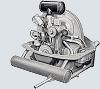
I cobbled together a simple pressure switch sender tonight. I found the threads on the sender to be 1/8" NPT and had fittings, a T and a pressure gauge on hand. I attached an air line fitting and ran it to a regulated tap off my compressor (not seen in the pics).
One of the switches I have seems to work. At first it would open as soon as I applied any air, but I took the terminal screw out and turned the adjuster in about 2-3 turns and I got it to stay closed (= dash light on) until I dialed it up to about 0.5 bar, which is a tad less than 0.5 atm. The sender is stamped "0.4 atm +/- 0.1" I think.
The other one "sticks" open like many I have found. Initially it is closed, but if I applied pressure (it opens), the release it, it doesn't close again. The Ohm meter drops to about 70-100 ohms however. If I tap the side of it with a wrench, it would close and drop to near 0 ohms.
Ideally, to set these things up, I'd like to get a gauge that went from 0 to 1 atm, not 0 to 11 like this one. I have just found another adjustable sender I will test tomorrow. I also have three senders with what looks like a 3/8" NPT thread (earlier?) and are adjustable. But I don't have the fittings to test them right now.
_________________
John Henry
'57 Deluxe
'56 Single Cab |
|
| Back to top |
|
|
Sunroof53
Samba Member

Joined: October 22, 2007
Posts: 301
Location: UK
|
| Posted: Sat Aug 28, 2010 3:32 pm Post subject: |
|
|
| The thread on the oil pressure switch is M10x1mm and not 1/8bspt.There are no imperial threads on a VW engine. |
|
| Back to top |
|
|
johnshenry
Samba Member
Joined: September 21, 2001
Posts: 9414
Location: Northwood, NH USA
|
| Posted: Thu Nov 11, 2010 8:23 am Post subject: |
|
|
I've been doing quite a lot of semaphore restoration lately and thought I would post some pics and details here. I only restore ribbed and grooved sems, I don't do anything with the smooth sems, except maybe scavenge an occasional part off of them when they are the same as on the earlier ones.
Restoring sems isn't rocket science, but there are some tricks and tips that are useful. Some of the tools and services might be available to folks who don't have them on their own. Let me also say that like many aspects of VWs, there are different ways to do things, and differing opinions on how things should be. I have been doing these for 5+ years now, and the biggest battle was finding sources for all of the parts and materials.
Descriptive text will follow each pic.
Here are a pair of '53 barndoor bus sems that I am doing for someone. These are very well patina'ed, but are excellent restoration candidates with usable arms and lenses. While I won't detail all of the aspects of the restoration of this particular pair, I do want to show them as an example of how a very original set of sems can be "brought back". A few more pics of them follow.
As is usually found: Multiple layers of paint on the arms.
Rusty, yes, but not too bad.
Here is perhaps what is more typically found. This is another set of SWF ribbed sems that I will show the complete restoration of. The rust is much deeper here and until these are completely taken apart, you really don't know how usable everything is. I think I paid $400 for this set of sems, in the condition shown, and today, that is actually a pretty good deal..
That's $400 with no arms, bulb holders and missing a bunch of hardware.
First order of business is to remove the pivot pin. In most all sems, it is shouldered on one end, and not the other. As such, one side's peened end will appear larger than the other. This is the "big" side. The other side looks similar but is smaller.
So the trick is to drill away the peened metal on the "small" side (shown above). I have seen countless sems with file and grind marks all over the side of the body. Yes, the edge of a dremel carbide disc works well too. But you don't want to leave a bunch of unsightly grinder marks on the body, so a drill works best. The pin is 3mm dia. a 1/8" drill bit (a sharp one!) works well. Drill just enough to get the sides of the bore flush with the body. You don't want to accidentally enlarge the hole in the body.
BTW, I have encountered some SWFs where both ends are shouldered. In this case you have to drill both sides, pry the body sides apart a bit, and "walk" the pivot and pin out.
The one lens with this set is in pretty good shape and original. It is a shame it is just cracked in a couple places. Good original lenses are very hard to find these days. I post a pic of it to point out the detail of an original lens: the side wall thickness is very thin, about .5mm and the little cone/barb near the lower bulbholder is smooth and has a point. Overall, the detail of the part is much better than any repro.
Another detail here to look at is the pivot arm. Since we don't have the original arms, we don't know if these sems were single screw, or dual screw (exposed screws on the arm, all were two screw really). But this pivot detail shows us that it is a 2 screw sem since the outermost screw hole is not beveled like the single screw ones where the second screw "hides" in the bevel underneath the arms. I'll post a pic of this detail on the barndoor ones which are single screw.
The pivot pin is driven out from the "small" side where the peened steel has been drilled away. Sometimes you don't have to, but it is usually a good idea to drill the big side a bit also before you drive the pin out. Support the sem body over some kind of cavity when driving the pin out, here I just use a nut.
Here you can see the pin removed from the sem. I know the pic is blurry, but you can see the shouldered end on the left. I do not re-use the pins, although it can be done if done properly. I make new pins for my restos.
Once the pin is out, the pivot arm and piston can be removed.
The retaining clip can be removed from the M6 screw using pliers. Don't lose it. These are one of the parts that I have hard time finding for restos when they are missing. I actually make them out of sheet spring steel, but good original ones are keepers.
To remove the coil and terminal board from the body, you need to drill a brass rivet out. A 3/16" drill bit works good for this. Again, the trick is to drill just enough away to remove the rivet.
You can pry the coil bracket up if needed to free the rivet. DO NOT pry between the terminal board and the coil bracket. The terminal boards break very easily, they are weak around the rivet hole, and are another hard to find in good shape part. Put the screwdriver blade between the coil bracket and the sem body as shown above.
Here is the coil and terminal board removed from the body. You can also see the coil end plate on the left. Some sems have a phenolic/fiberboard buffer that goes between the coil and the end plate, this one does not. On SHO sems (which are quite a bit different and MUCH more complicated) there is a very thin, round buffer there. One that breaks as easy as a potato chip... ask me how I know....
_________________
John Henry
'57 Deluxe
'56 Single Cab |
|
| Back to top |
|
|
johnshenry
Samba Member
Joined: September 21, 2001
Posts: 9414
Location: Northwood, NH USA
|
| Posted: Thu Nov 11, 2010 8:44 am Post subject: |
|
|
There are actually 3 springs in/on the pivot arm. The "snail shell" spring I have already taken off, there is a small linear spring inside the pivot arm that connects to the latch mechanism. The latch mechanism is what keeps the sems locked in the closed position so they don't "float" out at highway speed (ref.: the "Bernoulli principle"). I Buy dental pics at from the flea market too vendors, and they are invaluable for fishing these springs out (and re-installing them). If you spring is good, be very careful removing it. Another hard to find part. There are replacements (I think Wolfsburg West sells one now) but they are not the same, they are stronger and don't work as well.
The last of the 3 springs is a tall "U" spring that keeps pressure on the latch lever pivot. On the back of the pivot arm, you can see the bottom of this spring.
You can usually drive the end of this spring free of the tang in the pivot arm by tapping its bottom with a small screwdriver as shown above. Yes, you can also just drive the latch pivot pin out with the spring in place, but I find that to be one of those "parts go flying" maneuvers and I like to do it this way instead.
Here you can see the pivot arm/piston assembly disassembled. The 3 springs and the latch lever pivot pin at the top, the piston and the pivot arm. The "hook" end of the snail shell spring has broken off and this spring will need to be replaced.
_________________
John Henry
'57 Deluxe
'56 Single Cab |
|
| Back to top |
|
|
johnshenry
Samba Member
Joined: September 21, 2001
Posts: 9414
Location: Northwood, NH USA
|
| Posted: Thu Nov 11, 2010 10:35 am Post subject: |
|
|
The other sem is disassembled and in this pic you can see the large and small pivot pin holes.
Based on the condition of the lead wires and enamel on the coil windings, this one might have been cooked. When this happens, all of the enamel burns off the coil wires and the thing becomes basically a log of shorted copper.
I have extra coils, or I may just re-wind this one.
Everything taken apart on this pair. If you do one of these restos, keep all of the small parts in a baggie or box, it is real easy to lose stuff!!!
Some time in the media blasting cabinet, and the date code on the pivot arms can be read.
The first character is the month, A-M, I is not used.
The second character is the year, where:
1949=A, 1950=B, 1951=C, 1952=D, 1953=E, 1954=F, 1955=G, 1956=H, 1957=J, 1958=K, 1959=L, 1960=M, 1961=N, 1962=P, 1963=Q, 1964=R, 1965=S, 1966=T, 1967=U
I and O were not used.
So these sems (the codes match on this pair) are June 1952
The bodies and pivot arms are first stripped with aluminum oxide, then glass bead to smooth the pitting a bit. These are L-number sems, and are more valuable because of that. Post late '53, ribbed and grooved sems were still made as replacement parts but had "3x3" part numbers.
3mm dia tool steel is used to make new pivot pins.
Here's a little "Poor man's machining". After the stock is cut to length, one end is shouldered by running the Dremel carbide disc up against its end while it is spun in the drill press.
The ends of the new pins are then given a shallow "peen bore". Yes, you can drill the end of a 3mm piece of tool steel rod with a 1/16" drill bit IF the bit is very sharp!!
_________________
John Henry
'57 Deluxe
'56 Single Cab
Last edited by johnshenry on Thu Nov 11, 2010 11:58 am; edited 1 time in total |
|
| Back to top |
|
|
Zwitterkafer
Samba Member
Joined: November 17, 2007
Posts: 1012
Location: Lanark County, Ontario, Canada
|
| Posted: Thu Nov 11, 2010 11:39 am Post subject: |
|
|
Impeccable timing, John!
I need to make new pivot pins, and you just saved me some trial and error!
I have noticed that even a bit of play between the pivot pin and the semaphore arm bushing is not a good thing. The resulting slop in the semaphore arm travel could get bad enough to make it tough to prevent the arm from contacting the edges of the semaphore pocket in the door pillar.
Many thanks!
H.
_________________
"Criticism comes easier than Craftsmanship"
- Zeuxius, 400 BC |
|
| Back to top |
|
|
eurodub
Samba Member

Joined: August 05, 2007
Posts: 1321
|
| Posted: Thu Nov 11, 2010 2:04 pm Post subject: |
|
|
John, you never cease to amaze me. for a rookie that never disassembled a set of semaphore, your pics and explanations are all he needs.
the SWF ribbed sems are somewhat easy to restore with proper parts, a little custom work here and there. for me, ironically, the toughest thing to find was zinc plating for the arm and body.
i'll post pics soon in my thread too
_________________
1960 1200 model 117 deluxe ragtop
1976 MK1 Golf |
|
| Back to top |
|
|
ZwitterND
Samba Member
Joined: September 08, 2005
Posts: 1453
Location: Fargo, ND
|
| Posted: Thu Nov 11, 2010 7:27 pm Post subject: |
|
|
Thanks for sharing John I am positive you have saved me a few expletives when I rebuild er.. attempt to rebuild my SHO sems this winter. They are staring at me from across the room, taunting me, hope I don't go all Nicholson (The Shining) on them.
_________________
Bill |
|
| Back to top |
|
|
|


