| Author |
Message |
Jade
Samba Member
Joined: April 20, 2004
Posts: 70
Location: Houston, TX

|
|
| Back to top |
|
 |
NASkeet
Samba Member
Joined: April 29, 2006
Posts: 3168
Location: South Benfleet, Essex, UK
|
 Posted: Tue Jan 03, 2023 8:48 am Post subject: Retro-fitting vacuum brake-servo assistance Posted: Tue Jan 03, 2023 8:48 am Post subject: Retro-fitting vacuum brake-servo assistance |
 |
|
| aeromech wrote: |
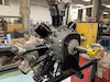
The 1971 bus manifold should look like this
|
The inlet manifold of my 1973 VW 1600 Type 2, AD-Series engine, lacked a half-inch vacuum connection spigot for a vacuum brake-servo unit. I had one welded on to the left-hand side of the inlet-manifold down-pipe, parallel to the inlet-manifold's horizontal pipes.
If I had known of the late-model VW Type 1 Beetle inlet manifold, with inlet-manifold, twin heater pipes from the exhaust system, to improve cold-weather performance and decrease the likelihood of inlet-manifold and carburettor icing (especially with the Minnow Fish carburettor), I might have elected to modify and use one of these instead!
VW Type 2, direct-acting, vacuum brake-servo units & associated hydraulic master cylinders, were not readily available in the late 1980s, here in Great Britain and I wasn't confident about being able to mount such a servo to the front suspension beam, at the appropriate angle.
Consequently, I retained all of the original factory-fitted hydraulic components and supplemented them with two ATE - Alfred Teves remote-acting, vacuum brake-servo units, of the same type that were factory-fitted to some right-hand drive BMW cars.
These were mounted in a home-made, square-section, tubular-steel cradle, suspended beneath the longitudinal chassis rails, rearward of the front jacking points, using existing holes in the chassis rails, to avoid introducing any additional stress concentrations (stress risers in USA parlance!?!).
Whilst I was making these modifications, including replacement of all the original factory-fitted, steel braking tubing with kinifer-10 brake tubing, I also replaced the factory-fitted two-terminal, hydraulic brake-light switches with three-terminal brake-light switches having the hydraulic brake-circuit failure, dashboard warning-light facility.
Here are the electrical circuits for the three-terminal, hydraulic brake-light switches, with early & late type, hydraulic brake-circuit failure, dashboard warning lights.
Early Type
a = black-cable connection to ignition-controlled supply terminal 15.
b = black/red-cable connection to rear brake lights
Late Type
A = electric switch inside brake-circuit-failure warning-light unit
B = 3-terminal brake-light switch
C = Dual-circuit brake warning lamp
a = blue cable to brake-circuit-failure warning-light unit's
internal switch-terminal 61 (shared with ignition warning light)
b = black cable to fuse-box terminal 15
c = brown cable to Earth (i.e. Ground in USA parlance)
d = black/red cable to brake lights
Afterwards, I had the brakes tested on a rolling-road, brake dynomometer, which is a standard, obligatory part of the annual MOT roadworthiness inspection.
_________________
Regards.
Nigel A. Skeet
Independent tutor (semi-retired) of mathematics, physics, technology & engineering for secondary, tertiary, further & higher education.
Much modified, RHD 1973 VW "1600" Type 2 Westfalia Continental campervan, with the World's only decent, cross-over-arm, SWF pantograph rear-window wiper
Onetime member, plus former Technical Editor & Editor of Transporter Talk magazine
Volkswagen Type 2 Owners' Club (Great Britain)
https://vwt2oc.co.uk |
|
| Back to top |
|
|
Bonesberg55
Samba Member
Joined: January 18, 2012
Posts: 1269
|
| Posted: Tue Jan 03, 2023 9:12 am Post subject: Re: How to: Install power brakes into 1968-1970 Bus (Pic heavy) |
|
|
| Nice conversion except compression fittings on brake lines are a no-no. You're looking at pressure of 500 psi and higher. I wouldn't trust any compression fittings and now most are made in China. |
|
| Back to top |
|
|
NASkeet
Samba Member
Joined: April 29, 2006
Posts: 3168
Location: South Benfleet, Essex, UK
|
| Posted: Wed Jan 04, 2023 8:35 am Post subject: Re: How to: Install power brakes into 1968-1970 Bus (Pic heavy) |
|
|
| Bonesberg55 wrote: |
| Nice conversion except compression fittings on brake lines are a no-no. You're looking at pressure of 500 psi and higher. I wouldn't trust any compression fittings and now most are made in China. |
To what compression fittings do you refer!?! 
I certainly did NOT use compression fittings for the hydraulic system, but I did use proper in-line hydraulic brake fittings, which required a taper to be formed at the end of the 3/16 inch Kunifer-10 brake tubing, using a special tool.
I undertook my conversion 34 years ago, during the winter of 1988/89, before the dawn of Internet shopping. It's doubtful whether any of the parts I used, would have been made in China!
To the best of my recall, there are twenty-three M10 x 1•0 mm brake unions in the rigid-pipe & flexible-hose system.
_________________
Regards.
Nigel A. Skeet
Independent tutor (semi-retired) of mathematics, physics, technology & engineering for secondary, tertiary, further & higher education.
Much modified, RHD 1973 VW "1600" Type 2 Westfalia Continental campervan, with the World's only decent, cross-over-arm, SWF pantograph rear-window wiper
Onetime member, plus former Technical Editor & Editor of Transporter Talk magazine
Volkswagen Type 2 Owners' Club (Great Britain)
https://vwt2oc.co.uk
Last edited by NASkeet on Sat Jan 07, 2023 12:09 pm; edited 1 time in total |
|
| Back to top |
|
|
Bonesberg55
Samba Member
Joined: January 18, 2012
Posts: 1269
|
| Posted: Wed Jan 04, 2023 8:49 am Post subject: Re: How to: Install power brakes into 1968-1970 Bus (Pic heavy) |
|
|
| NASkeet wrote: |
| Bonesberg55 wrote: |
| Nice conversion except compression fittings on brake lines are a no-no. You're looking at pressure of 500 psi and higher. I wouldn't trust any compression fittings and now most are made in China. |
To what compression fittings do you refer!?!
I certainly did NOT use compression fittings for the hydraulic system, but I did use proper in-line hydraulic brake fittings, which required a taper to be formed at the end of the 3/16 inch Kunifer-10 brake tubing, using a special tool.
I undertook my conversion 34 years ago, during the winter of 1988/89, before the dawn of Internet shopping. It's doubtful whether any of the parts I used, would have been made in China!
To the best of my recall, there are twenty-three M10 x 1•0 mm brake unions in the rigid-pipe & flexible-hose system. |
Sorry if I'm mistaken, but in your 8th photo down it looks to me like the 2 unions shown are compression fittings. |
|
| Back to top |
|
|
KTPhil 
Samba Member

Joined: April 06, 2006
Posts: 35706
Location: Conejo Valley, CA
|
| Posted: Wed Jan 04, 2023 9:19 am Post subject: |
|
|
| aeromech wrote: |
The 1971 bus manifold should look like this
|
I have to laugh at this pic. Over the holidays I painted my HEs, shroud parts, tins, etc, and hung them on branches in the front yard to dry.
I am sure neighbors thought I had a real sickness, decorating a Christmas tree with VW parts!  |
|
| Back to top |
|
|
NASkeet
Samba Member
Joined: April 29, 2006
Posts: 3168
Location: South Benfleet, Essex, UK
|
| Posted: Sat Jan 07, 2023 12:20 pm Post subject: Re: How to: Install power brakes into 1968-1970 Bus (Pic heavy) |
|
|
| Bonesberg55 wrote: |
| NASkeet wrote: |
| Bonesberg55 wrote: |
| Nice conversion except compression fittings on brake lines are a no-no. You're looking at pressure of 500 psi and higher. I wouldn't trust any compression fittings and now most are made in China. |
To what compression fittings do you refer!?!
I certainly did NOT use compression fittings for the hydraulic system, but I did use proper in-line hydraulic brake fittings, which required a taper to be formed at the end of the 3/16 inch Kunifer-10 brake tubing, using a special tool.
I undertook my conversion 34 years ago, during the winter of 1988/89, before the dawn of Internet shopping. It's doubtful whether any of the parts I used, would have been made in China!
To the best of my recall, there are twenty-three M10 x 1•0 mm brake unions in the rigid-pipe & flexible-hose system. |
Sorry if I'm mistaken, but in your 8th photo down it looks to me like the 2 unions shown are compression fittings. |
If you were referring to the in-line pipe connectors, in the lower of the two following line-drawings, they were special female-female hydraulic connectors, which connected at either end with male unions & flared 3/16 inch Kunifer-10 brake tubing. I bought them from my local specialised clutch & brake centre.
In-line, 25 mm long, M10 x 1·0 mm, female-female, in-line, metric, brake-pipe connectors of this type (labelled B in the following cross-sectional illustration), were also used in the creation of my home-made, oil-pressure, gauge-sender, installation adapter, which I have fabricated for use, on the VW Type 4 engine.
_________________
Regards.
Nigel A. Skeet
Independent tutor (semi-retired) of mathematics, physics, technology & engineering for secondary, tertiary, further & higher education.
Much modified, RHD 1973 VW "1600" Type 2 Westfalia Continental campervan, with the World's only decent, cross-over-arm, SWF pantograph rear-window wiper
Onetime member, plus former Technical Editor & Editor of Transporter Talk magazine
Volkswagen Type 2 Owners' Club (Great Britain)
https://vwt2oc.co.uk |
|
| Back to top |
|
|
75 Westy FI noob
Samba Member
Joined: November 04, 2022
Posts: 396
Location: MidWest
|
| Posted: Wed Feb 22, 2023 9:36 am Post subject: Re: How to: Install power brakes into 1968-1970 Bus (Pic heavy) |
|
|
Very nice write up…
Anyone know if the reservoirs are interchangeable?
The full nipple on mine is perpendiculars to the master and very close to the frame. Makes attaching the hose impossible without removing the reservoir, which will not come off… so i will have to remove the master…
Kids cracked the upper reservoir… sent me down this unpleasant rabbit hole.
But they had fun ‘driving’ so… i guess its the price to pay |
|
| Back to top |
|
|
kreemoweet
Samba Member
Joined: March 13, 2008
Posts: 4077
Location: Seattle, WA
|
| Posted: Wed Feb 22, 2023 11:03 am Post subject: Re: How to: Install power brakes into 1968-1970 Bus (Pic heavy) |
|
|
| 75 Westy FI noob wrote: |
| Anyone know if the reservoirs are interchangeable? |
Interchangeable between what and what?
Sounds like you have the 73-79 bus reservoir. The 71-72 reservoir nipple points to the rear.
The earlier bus reservoirs have a different spacing between the M/C inlets, so no go for a power brake M/C.
There's a good deal of confusion regarding the different reservoirs amongst vendors.
The original 71-72 reservoir had part #211-611-313J.
Some vendors are selling (or used to) genuine VW 71-72 reservoirs which bear the number 211 611313 5.
_________________
'67 bug: seized by the authorities
'68 bug: seized by the authorities
'71 kombi: not yet seized by the authorities
Stop dead photo links! Post your photos to The Samba Gallery! |
|
| Back to top |
|
|
75 Westy FI noob
Samba Member
Joined: November 04, 2022
Posts: 396
Location: MidWest
|
| Posted: Thu Feb 23, 2023 2:02 pm Post subject: Re: How to: Install power brakes into 1968-1970 Bus (Pic heavy) |
|
|
| was wondering if a different reservoir could be fitted.. with a longitudinal nipple. i'm gonna try to pop mine off one more time and replace it (because i'm pretty sure removal is gonna damage it) it's stuck tighter than a tick on there. rather not remove the master unless i have to. |
|
| Back to top |
|
|
aeromech
Samba Member
Joined: January 24, 2006
Posts: 17601
Location: San Diego, California
|
| Posted: Thu Feb 23, 2023 9:23 pm Post subject: Re: How to: Install power brakes into 1968-1970 Bus (Pic heavy) |
|
|
| Bonesberg55 wrote: |
| Nice conversion except compression fittings on brake lines are a no-no. You're looking at pressure of 500 psi and higher. I wouldn't trust any compression fittings and now most are made in China. |
Think again
https://products.swagelok.com/en/all-products/fittings/tube-fittings-adapters/c/154?clp=true
_________________
Lead Mechanic: San Diego Air and Space Museum
Licensed Airframe and Powerplant Mechanic
Licensed Pilot (Single engine Land)
Boeing 727,737-200-300-400,757,767
Airbus A319,320,321
DC9/MD80
BAe146
Fokker F28/F100
VW type 1 1962,63,65,69,72
VW Type 2 1971 (3 ea.) 1978, 1969
VW Jetta
VW Passat
Capable of leaping tall buildings in a single bound |
|
| Back to top |
|
|
NASkeet
Samba Member
Joined: April 29, 2006
Posts: 3168
Location: South Benfleet, Essex, UK
|
| Posted: Fri Feb 24, 2023 1:18 pm Post subject: Re: How to: Install power brakes into 1968-1970 Bus (Pic heavy) |
|
|
Interesting!
I might consider something like that for my 1974 Triumph Toledo 1300 "HL Special", when I get around to overhauling the braking system, replacing the hoses & pipework and converting from single-circuit to dual-circuit hydraulic master cylinder.
_________________
Regards.
Nigel A. Skeet
Independent tutor (semi-retired) of mathematics, physics, technology & engineering for secondary, tertiary, further & higher education.
Much modified, RHD 1973 VW "1600" Type 2 Westfalia Continental campervan, with the World's only decent, cross-over-arm, SWF pantograph rear-window wiper
Onetime member, plus former Technical Editor & Editor of Transporter Talk magazine
Volkswagen Type 2 Owners' Club (Great Britain)
https://vwt2oc.co.uk |
|
| Back to top |
|
|
mack00
Samba Member
Joined: October 28, 2005
Posts: 174
Location: marietta georgia usa
|
| Posted: Tue Apr 25, 2023 1:39 pm Post subject: Re: How to: Install power brakes into 1968-1970 Bus (Pic heavy) |
|
|
| I’ve started acquiring parts to add this mod to my 69 single cab. Ordered master cylinder 211611021AABR. Reservoir 211611313J. The vendor shows these effective to 71 with servo. MC has reservoir inlets at 85mm spacing. The reservoir outlet nipples are 100mm. The reservoir does have the inlet pointing straight back on the drivers side. Which part is incorrect? Any sources for the correct parts? |
|
| Back to top |
|
|
kreemoweet
Samba Member
Joined: March 13, 2008
Posts: 4077
Location: Seattle, WA
|
| Posted: Tue Apr 25, 2023 5:19 pm Post subject: Re: How to: Install power brakes into 1968-1970 Bus (Pic heavy) |
|
|
| mack00 wrote: |
| I’ve started acquiring parts to add this mod to my 69 single cab. Ordered master cylinder 211611021AABR. Reservoir 211611313J. The vendor shows these effective to 71 with servo. MC has reservoir inlets at 85mm spacing. The reservoir outlet nipples are 100mm. The reservoir does have the inlet pointing straight back on the drivers side. Which part is incorrect? Any sources for the correct parts? |
Your reservoir is wrong. All 71-79 busses with servo used the m/c you have (except made in Germany of course), with inlet spacing 85 mm. The later bus (73 - on?) reservoirs had a different hose nipple than the 71-72?. I have a new Genuine VW '71 bus reservoir with part #211-611-313-5 on it. I'm not sure where I got it, either busdepot.com or wolfsburgwest.com.
_________________
'67 bug: seized by the authorities
'68 bug: seized by the authorities
'71 kombi: not yet seized by the authorities
Stop dead photo links! Post your photos to The Samba Gallery! |
|
| Back to top |
|
|
airschooled
Air-Schooled

Joined: April 04, 2012
Posts: 13417
Location: West Coast, USA
|
|
| Back to top |
|
|
NASkeet
Samba Member
Joined: April 29, 2006
Posts: 3168
Location: South Benfleet, Essex, UK
|
| Posted: Wed Apr 26, 2023 1:22 am Post subject: Re: How to: Install power brakes into 1968-1970 Bus (Pic heavy) |
|
|
| airschooled wrote: |
metahacker turned me on to this great mount, which allows a stock booster to bolt on to a non-servo beam. Even after shipping to the US it's cheaper than having a mobile welder out for an hour or two, and allows small lateral adjustments to mitigate parking brake cable rub. Very cool.
https://limebug.com/product/t2-1968-79-bolt-on-brake-servo-mount/ |
It's amazing the things we British come up with, even in Stoke-on-Trent; formerly the spiritual home of the potteries! 
If that item including shipping was cheaper than 1~2 hours work from a mobile welder, your American workers must be over-burdened with money these days!?!
_________________
Regards.
Nigel A. Skeet
Independent tutor (semi-retired) of mathematics, physics, technology & engineering for secondary, tertiary, further & higher education.
Much modified, RHD 1973 VW "1600" Type 2 Westfalia Continental campervan, with the World's only decent, cross-over-arm, SWF pantograph rear-window wiper
Onetime member, plus former Technical Editor & Editor of Transporter Talk magazine
Volkswagen Type 2 Owners' Club (Great Britain)
https://vwt2oc.co.uk |
|
| Back to top |
|
|
mack00
Samba Member
Joined: October 28, 2005
Posts: 174
Location: marietta georgia usa
|
| Posted: Wed Apr 26, 2023 4:04 am Post subject: Re: How to: Install power brakes into 1968-1970 Bus (Pic heavy) |
|
|
| kreemoweet wrote: |
| mack00 wrote: |
| I’ve started acquiring parts to add this mod to my 69 single cab. Ordered master cylinder 211611021AABR. Reservoir 211611313J. The vendor shows these effective to 71 with servo. MC has reservoir inlets at 85mm spacing. The reservoir outlet nipples are 100mm. The reservoir does have the inlet pointing straight back on the drivers side. Which part is incorrect? Any sources for the correct parts? |
Your reservoir is wrong. All 71-79 busses with servo used the m/c you have (except made in Germany of course), with inlet spacing 85 mm. The later bus (73 - on?) reservoirs had a different hose nipple than the 71-72?. I have a new Genuine VW '71 bus reservoir with part #211-611-313-5 on it. I'm not sure where I got it, either busdepot.com or wolfsburgwest.com. |
Thanks for the part# info. I did reach out to Busdepot. The one they offer is incorrect also. I think our wonderful classifieds came through again.
Now i need the rod between pedal & sevro. How much does it need lengthened? Can a threaded bolt just be welded on?
https://limebug.com/product/t2-1968-79-bolt-on-brake-servo-mount/
This does appear to be a quality bolt on option. I already have a plate to weld in. |
|
| Back to top |
|
|
kreemoweet
Samba Member
Joined: March 13, 2008
Posts: 4077
Location: Seattle, WA
|
| Posted: Wed Apr 26, 2023 10:06 am Post subject: Re: How to: Install power brakes into 1968-1970 Bus (Pic heavy) |
|
|
The BusDepot reservoir looks correct to me, it's the same as the original reservoir on my '71 and the new replacement I have. Why do you say it's wrong? Does BD have the wrong part image there?
The push bar that goes into the booster is threaded, and any length adjustment is made there (part #211-721-291A). The brake pedal lever under the floor is evidently also different than the one on non-boostered busses. That would be part #211-721-141C on 71-79 US (w/servo) bus.
_________________
'67 bug: seized by the authorities
'68 bug: seized by the authorities
'71 kombi: not yet seized by the authorities
Stop dead photo links! Post your photos to The Samba Gallery! |
|
| Back to top |
|
|
mack00
Samba Member
Joined: October 28, 2005
Posts: 174
Location: marietta georgia usa
|
| Posted: Wed Apr 26, 2023 10:51 am Post subject: Re: How to: Install power brakes into 1968-1970 Bus (Pic heavy) |
|
|
I agree the picture is correct but the spacing is 100mm. Same as the other vendor I'm dealing with.
The original post states the rod needs to be lengthened 1 inch. Did you not require this? It probably depends where the plate that attaches the servo is welded in. |
|
| Back to top |
|
|
kreemoweet
Samba Member
Joined: March 13, 2008
Posts: 4077
Location: Seattle, WA
|
| Posted: Wed Apr 26, 2023 1:10 pm Post subject: Re: How to: Install power brakes into 1968-1970 Bus (Pic heavy) |
|
|
| mack00 wrote: |
I agree the picture is correct but the spacing is 100mm. Same as the other vendor I'm dealing with.
The original post states the rod needs to be lengthened 1 inch. Did you not require this? It probably depends where the plate that attaches the servo is welded in. |
Well that makes no sense, there's no disk brake m/c on busses that has a fill port spacing of 100 mm. And I don't think any of the 100 mm reservoirs look anything like the 71-72 one. Perhaps the person you spoke with is unable to tell the difference?
I looked thru my old invoices, and I did get my 100% correct reservoir from BD in Sep 2014, same part #. I'm betting on ignorant or dishonest salesperson at BD.
The "lengthening" of the servo push bar likely has to due with the difference in the earlier non-servo brake pedal lever. Of course
that would all be irrelevant to anyone with a stock US '71 brake setup, like myself.
_________________
'67 bug: seized by the authorities
'68 bug: seized by the authorities
'71 kombi: not yet seized by the authorities
Stop dead photo links! Post your photos to The Samba Gallery! |
|
| Back to top |
|
|
|


