| Author |
Message |
BulliBill
Samba Member
Joined: July 09, 2004
Posts: 4614
Location: St Charles, MO

|
 Posted: Fri Apr 24, 2015 9:34 am Post subject: Posted: Fri Apr 24, 2015 9:34 am Post subject: |
 |
|
Howdy folks,
What with the recent passing of great friend Brian Holcomb, work, life in general, and also spending five days out in Nor Cal for the Kelley Park festivities, progress on the DC has recently been slow. Brian's memorial service will be next weekend, so we'll be headed up to WI for a long weekend there. I need to get the flasher system tested and discover what the issue is and fix it, then get the 36hp motor installed.
In the meantime, two questions...
While testing the circuits, I imagine that there should be no problem leaving the ignition switch "on" for periods of a few minutes at a time since the engine is not installed, correct? No coil or points to fry... If wrong, let me know, as I don't want to cook anything during testing.
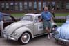
Also, I have to renew my collectors insurance policy on this 1959 Double-Cab this week. For those who have been following this build thread and are aware of the quality of the work and parts involved, I'd be curious to hear from you what you think the replacement valve of this DC might be, as I think I need to bump up it's current valuation with the insurance company (Grundy Worldwide). If the worst were to happen and I incurred a total loss of the vehicle, I'd want to be compensated, as that is why we all pay those premiums every year. Just curious as to what your estimate might be... Guesses ought to be all over the place, but I'll need to come to some consensus and alter the policy a little.
Bill
_________________
I'm looking for these license plate frames for my fleet:
Coeur D'Alene - Lake Shore Volkswagen
Mission VW - San Fernando
Thornton VW - Stockton
Thanks for any help!
Last edited by BulliBill on Sat May 23, 2015 8:11 am; edited 2 times in total |
|
| Back to top |
|
 |
BarryL 
Samba Member
Joined: November 01, 2004
Posts: 14456
Location: Casa de Oro, California

|
| Posted: Fri Apr 24, 2015 9:53 am Post subject: |
|
|
| BulliBill wrote: |
| there should be no problem leaving the ignition switch "on" for periods of a few minutes at a time since the engine is not installed, correct? No coil or points to fry.. |
Totally OK. Just remember it is not a fused circuit until after it enters the "key on" fused circuits. |
|
| Back to top |
|
|
BulliBill
Samba Member
Joined: July 09, 2004
Posts: 4614
Location: St Charles, MO
|
| Posted: Mon Apr 27, 2015 9:14 pm Post subject: |
|
|
I'm back in town for a few days, and spent some time today trying out a few of the above test procedures suggested above. I made up some nice jumper wires with alligator clips for easier testing. The used "screw-connector" style blinker relay is mounted to the back of the fuse box screw. Here is what I have tried and the results.
In the photo above, you can see the used 6 volt relay with my green jumper wire with black plastic covered alligator clip ends.
Here are the three terminals that I have on the used 6 volt blinker relay that I installed:
terminal #15 which has switchable and fused 6 volt power from the ignition switch through the fuse box and into the relay terminal #15;
terminal #54 which is the wire that carries power out and away from the relay and on to the turn signal switch mounted on the steering column;
and a terminal with no number or symbol markings, to which the blue wire with a green strip leads away from the relay terminal and over to the speedometer warning light for the turn signal.
The relay is grounded to the body through it's mounting bracket which is screwed to the left mounting screw on the fuse box.
Okay, with the ignition key switched "off", there is no power to any of the three terminals on the blinker relay.
When the ignition key is turned to "on", I now have 6 volt power at the #15 terminal. No power at all at #54 terminal or to the terminal with the blue wire with the green stripe.
With the key still "on", and when I operate the turn-signal switch to the right or left, still no power at #54 or the terminal with the blue wire with the green stripe.
As suggested above, I turned the turn signal switch to the middle "neutral" or "off" position. I then clipped a jumper wire end to terminal #15 and #54. Naturally I've now brought 6 volt power through the jumper wire and I now have 6 volt power at both terminals #15 and #54. Still no power at all on the terminal with the blue wire with the green stripe, and no blinking or solid red turn signal light at all in the speedometer. No clicks or hums from the relay canister, none of the turn signal lights come on at all. I'm assuming that if my used relay was functioning properly, at this point I should have fully functional flashing turn signal warning lights at all four corners, a flashing warning red light in the speedometer and I'd be hearing a clicking sound from the relay, correct?
Then as suggested, with the ignition switch "on" and the jumper wire clipped to #15 and #54, I then operated the turn signal to the right and left turn positions. When I did so, no click or hum form the canister but the light bulbs in the front and rear turn signal assemblies for the appropriate side light up solid and bright (no blinking). Yea! But no blinking at all, and no blinking or solid red turn signal light at all in the speedometer.
Okay, so what's up? I'm guessing the old, used relay is kaput? Anyone out there love to tinker with and repair these things, as I'd love to have a working "screw-terminal" blinker canister on this beast? Any prognosis based on my tests above?
Since I don't have any more "screw-connector" style relays around, I find that I only have a few "spade-connector" style blinker relay canisters lying about. See my photos below of two different "later style canisters that I have in house. All seem to be grounded through the canister housing via a threaded stud or a metal clip. Some have only two terminals, and others have three terminals. Only one of my extras has terminals #15, #54 and "K" for "Kontrolle". Others have terminals #49A, #+49 and either "-" or #31. Others have #31, S and "+". Oh man!!! What to do, what to use?
Any of you electrical wizards understand what I've described and can maybe give me (and other future readers) a guide to what to do next? I can't wait to hear what you think about my pesky issue...
Thanks!
Bill
_________________
I'm looking for these license plate frames for my fleet:
Coeur D'Alene - Lake Shore Volkswagen
Mission VW - San Fernando
Thornton VW - Stockton
Thanks for any help!
Last edited by BulliBill on Fri Jun 19, 2015 9:17 am; edited 2 times in total |
|
| Back to top |
|
|
glideking
Samba Member

Joined: February 02, 2013
Posts: 990
Location: California
|
| Posted: Mon Apr 27, 2015 9:59 pm Post subject: |
|
|
Have you bench tested the flasher on your workbench with a single bulb clip leaded to 6v?
The old contacts on the flasher do get oxidized. More so when they are not in use for a long time. They can be cleaned if you can get the can open without damaging it. Since you hear no clicking then it could be the bi metal heat element inside with it's own contacts that need to be cleaned. Sometimes you can get them to work by banging them on the table while in a circuit. Part of the problem with 6v contacts vs 12v is a smaller arc to get those contacts working. Remember having to bang on the old radios to get them to work. That actually does work Unlike modern solid state devices.
When I restore old vacuum tube guitar amps I like to keep the old capacitor cans to keep them stock looking. The life span of an electrolytic capacitor is 10 to 20 years. Many guitar amps are 50 years old. Modern capacitors are much smaller so I cram the new replacement capacitors into the old cans and reinstall them.
I will be keeping my old screw terminal flasher for my '59 too. A modern flasher will fit inside. It is a time consuming fiddly thing to do but it is fun.
Nice closeup photos Bill.
Kurt
_________________
"The more I get done the less it looks like I did anything"
1959 Single Cab Restoration"Funky Truck"
http://www.thesamba.com/vw/forum/viewtopic.php?t=5...highlight=
1965 21 Window Restoration Thread (From old photos)
http://www.thesamba.com/vw/forum/viewtopic.php?t=6...highlight=
1963 Panelvan build "Tyvanosaurus Wrecks"
http://www.thesamba.com/vw/forum/viewtopic.php?p=8351639#8351639 |
|
| Back to top |
|
|
BarryL
Samba Member
Joined: November 01, 2004
Posts: 14456
Location: Casa de Oro, California
|
| Posted: Tue Apr 28, 2015 9:38 am Post subject: |
|
|
| Bill, with the jumper you proved the circuit is good but the flasher in not contacting internally to close the circuit you just imitated. Pry open the flasher and clean the contacts or replace the flasher. |
|
| Back to top |
|
|
Suboval
Samba Member
Joined: September 15, 2003
Posts: 794
|
| Posted: Tue Apr 28, 2015 3:32 pm Post subject: |
|
|
Since you have new paint, how is the relay grounding? That relay needs to be properly grounded for it to work.
Also, you can sometimes get those relays to work by turning on the turn signal signals and rapping the outside of the relay with the handle end of the screwdriver. It is a bimetallic relay and current is the key to making them work.
BTW, did get my PM?
_________________
It all works on paper.
There's two things we learn from history:
1.) History repeats itself.
2.) We don't learn from history. |
|
| Back to top |
|
|
BulliBill
Samba Member
Joined: July 09, 2004
Posts: 4614
Location: St Charles, MO
|
| Posted: Wed Apr 29, 2015 6:12 am Post subject: |
|
|
Hard to tell from the photo above, but that used and installed screw-terminal relay has a built in metal mounting bracket which attaches to the back of the fuse box via on of the two mounting screws that attach the fuse box to the fuse box bracket. I guess I could try it again and try to temporarily better ground the relay to see if there is any improvement. I tried lightly rapping the canister with a screwdriver handle as suggested but got no improvement.
Kurt, or anyone, is there a easy way to "bench test" (out of the VW, you know, on a work bench) any of these blinker relays? Could someone describe in simple terms the process, tools and test equipment needed and what to look for/expect? That would be helpful to both myself and many others who might have extra turn signal relays lying about...
Thanks for the help and suggestions!
Bill
_________________
I'm looking for these license plate frames for my fleet:
Coeur D'Alene - Lake Shore Volkswagen
Mission VW - San Fernando
Thornton VW - Stockton
Thanks for any help! |
|
| Back to top |
|
|
Loren
Samba Member

Joined: January 10, 2004
Posts: 1724
|
| Posted: Wed Apr 29, 2015 9:12 am Post subject: |
|
|
| My 59 Ghia has a similar screw terminal flasher relay and the blinkers didn't work very well when I got the car. After some experimentation I found that an extra ground wire from the flasher relay ground terminal to the body fixed my blinker issues. May not work on your situation, but it's worth a try. |
|
| Back to top |
|
|
BulliBill
Samba Member
Joined: July 09, 2004
Posts: 4614
Location: St Charles, MO
|
| Posted: Wed Apr 29, 2015 10:25 am Post subject: |
|
|
Thanks Loren,
That'll be my next simple test before removing/replacing that screw-terminal blinker relay.
Bill
_________________
I'm looking for these license plate frames for my fleet:
Coeur D'Alene - Lake Shore Volkswagen
Mission VW - San Fernando
Thornton VW - Stockton
Thanks for any help! |
|
| Back to top |
|
|
BulliBill
Samba Member
Joined: July 09, 2004
Posts: 4614
Location: St Charles, MO
|
| Posted: Tue May 05, 2015 5:45 pm Post subject: |
|
|
Okay, today I had a little time to spend on the DC electrical system.
First off, I thought I'd try to add an extra ground to the used "screw-terminal" canister that is already in place, but not working properly. I crossed my fingers and clipped on an alligator jumper wire to the body of the canister and to a known good ground point. Damn! No improvement!
Bummer!
So it was time to remove the screw-terminal canister and temporarily rig up a later "spade-terminal" canister. I removed the used one and here are a few shots of it. Notice that the canister has a built-in metal bracket which attaches to the left side screw on the forward most side of the fuse box. This point serves as it's grounding point...
You can see the "K", "S" and "-" connectors on the bottom side.
I noticed the brand and info markings on it in the above photos. This is an "SWF" brand marked 6 volt 2x20W
The later relay has a self-threading threaded stud on it's top of the canister. For my testing purposes I had to ground the new canister with a wire to the good ground point on the chassis. That brown wire and green wire are actually connected to become the ground for the canister.
Below are the markings on the canister. As you can see, the newer canister is a 6 volt 2 x 18W model...
I used a few old used wires with spade connectors on them and a couple of "screw-terminal" wire junction strips to temporarily rig up the wiring.
And here are the "K", "+15" and "S54" marked terminals on the bottom of the newer canister.
So it was time to test the new relay out. I went to the engine compartment and re-attached the battery leads. I turned the ignition switch to "on" (remember, the 36hp engine isn't yet installed so I wasn't in peril of damaging the coil or distributor). Then I held my breath and operated the turn signal lever to left turn and listened. There was a slow clicking from the new relay, but it was definitely clicking! The outer left front and rear turn signal light assemblies were slowly blinking! Same thing happened when I tried the right turn position! We've got blinkers, albeit slow ones! Woo Hoooo!
The only issue now is that the red warning light in the trip speedometer is not blinking on and off. Not sure what is up there. Any ideas from you experts out there on how to test that speedo warning light? The bulb is new, I tested it for continuity/function before installing it in the speedo as I did with all of the brand new bulbs on the Double-Cab.
A few more questions as I prepare to go back in and more permanently wire up this new relay.
1. Does the canister have to be hanging upright? Can it be mounted sideways or in any orientation?
2. Is there a big difference in switching from a 6 volt 2x20W canister to a 2x18W newer flasher canister?
Thanks for any ideas on how to best proceed.
Bill
_________________
I'm looking for these license plate frames for my fleet:
Coeur D'Alene - Lake Shore Volkswagen
Mission VW - San Fernando
Thornton VW - Stockton
Thanks for any help! |
|
| Back to top |
|
|
Suboval
Samba Member
Joined: September 15, 2003
Posts: 794
|
| Posted: Wed May 06, 2015 8:00 am Post subject: |
|
|
Since these relays are thermal bimetallic relays, they are dependent upon current. You can adjust it. Just remove the brown circle sticker and there is a small adjustment screw underneath there.
It can be mounted in any direction. I would do any final adjustment with the engine on.
You can test the speedometer light by turning on the ignition and grounding the blue wire. The light should come on.
_________________
It all works on paper.
There's two things we learn from history:
1.) History repeats itself.
2.) We don't learn from history. |
|
| Back to top |
|
|
BarryL
Samba Member
Joined: November 01, 2004
Posts: 14456
Location: Casa de Oro, California
|
| Posted: Wed May 06, 2015 10:09 am Post subject: |
|
|
| BulliBill wrote: |
the screw-terminal canister.
1. Does the canister have to be hanging upright? Can it be mounted sideways or in any orientation?
2. Is there a big difference in switching from a 6 volt 2x20W canister to a 2x18W newer flasher canister?
Thanks for any ideas on how to best proceed.
Bill |
a. Carefully pry the lip off the old one, pull off the cover, and you most likely will be able to clean the contacts and reuse it.
b. You can use the stud on the new canister to go into the old bracket.
c. You can use your old screw and nut/holder on the new spades by drilling. They almost all have a pilot hole per tab.
1. Canister can be in any direction but contacts down is best for condensation non entry.
2. Not much difference in wattage handling but after the generator is running they will blink faster.
3. According to the diagram on the new canister you have the correct type. Try what Suboval said first. The dash indicator non working could be because of the + vs - style signal. To test if you have the wrong polarity style sender, unhook the switched B+ from your canister and jump a hot B+ to it and see if the speedo light illuminates with the key off when signalling. |
|
| Back to top |
|
|
BulliBill
Samba Member
Joined: July 09, 2004
Posts: 4614
Location: St Charles, MO
|
| Posted: Thu May 07, 2015 12:38 pm Post subject: |
|
|
You guys are amazing! I admire your electrical knowledge, and your willingness to share it with those of us who suspect there is really just a wizard with a cone hat and magic wand inside our electrical components! I'm currently out flying for AA ( in a broken MD-80 in Columbus, Ohio right now, any of you wanna come over and work on the hydralic system?) in a downtown hotel waiting for the call back to the airport. Whenever we get home, I'll give your suggestions at try!
Thanks again for your advice!
Bill
_________________
I'm looking for these license plate frames for my fleet:
Coeur D'Alene - Lake Shore Volkswagen
Mission VW - San Fernando
Thornton VW - Stockton
Thanks for any help! |
|
| Back to top |
|
|
easy e
Samba Member

Joined: May 28, 2008
Posts: 3937
Location: 1 hr north of Santa Barbara
|
| Posted: Thu May 07, 2015 2:36 pm Post subject: |
|
|
Bill,
I've enjoyed your thread a lot & hearing about the NOS bits you've been saving for X years & the various parts getting the loving attention they deserve... are those lenses what I think they are? If so, holler out & I'm sure some of the fans watching your build will get you hooked up.
_________________
aka: Evan
Spreadsheet for Bus RPM, based on gearing & tire size (Excel format)
Searchable, click-navigable 1958 Bus Parts List |
|
| Back to top |
|
|
Who.Me?
Samba Member

Joined: July 14, 2014
Posts: 2257
Location: UK (South)
|
| Posted: Fri May 08, 2015 12:44 am Post subject: |
|
|
| BulliBill wrote: |
| those of us who suspect there is really just a wizard with a cone hat and magic wand inside our electrical components! |
Living very close to a major airport, it worries me when I hear pilots say things like that. Aren't you supposed to be omniscient?  |
|
| Back to top |
|
|
BulliBill
Samba Member
Joined: July 09, 2004
Posts: 4614
Location: St Charles, MO
|
| Posted: Sat May 09, 2015 5:46 pm Post subject: |
|
|
| Who.Me? wrote: |
| BulliBill wrote: |
| those of us who suspect there is really just a wizard with a cone hat and magic wand inside our electrical components! |
Living very close to a major airport, it worries me when I hear pilots say things like that. Aren't you supposed to be omniscient? |
You can relax a little "Who.me.", as I'm not the one behind the controls of the aircraft flying over your house. I've been a flight attendant for about 38 years now (I started flying for TWA back in June of 1976). Oh! The stories I could tell! I'm the one who can serve you a beverage in flight, defibrillate you during a heart attack, or toss you and a few hundred others safely out of the aircraft in an emergency landing in less than 90 seconds... I don't have to know a lot about electricity (I do know the basics), but I can sure help and motivate scared people when needed. I'm just glad there are others out there who really know this automotive electrical stuff and how to test and diagnose issues and seem happy to help others out. Now... put your damn cellphone in "airplane mode"... please. LOL
Hey "easy e", Yep, good eye! Those are plastic lens that I put on that DC about 22 years ago once I bought it. It had one good and one cracked glass lens. I currently have a few good glass lens, but none are matched, so for now I just installed the plastic lenses with "KDF" brand markings from back in the early 1990's. Yeah, I hope to put together a reasonably priced matching pair of "original" glass lenses for this DC someday. I guess I need to be looking for the "early" diamond-style SRBL 17 lenses to eventually get this correct.
Bill
_________________
I'm looking for these license plate frames for my fleet:
Coeur D'Alene - Lake Shore Volkswagen
Mission VW - San Fernando
Thornton VW - Stockton
Thanks for any help! |
|
| Back to top |
|
|
BulliBill
Samba Member
Joined: July 09, 2004
Posts: 4614
Location: St Charles, MO
|
| Posted: Sat May 23, 2015 8:10 am Post subject: |
|
|
A big thank you goes out to "easy e", who spotted my round plastic tail light lenses in the photo above. He must like this build thread for this DC, because he then went above and beyond the call, and for a very reasonable price offered to hook me up with one of the correct original glass "early" SRBL17 lenses from his stash so that eventually I can install a correct pair on the butt-end of this big, blue DC. Thanks so much Evan! So now I'll be keeping an eye out for another one to complete the pair and then get them onto the Bus.
So to continue with the blinker saga, I decided to use an NOS later spade terminal blinker relay rigged up temporarily to test the system, and sure enough, the blinkers functioned properly, although slowly. The only issue I am still having is that the red warning light in the speedometer still wont light up or flash. I pulled and tested the 6 volt bulb and it works fine.
I decided for now to use this NOS relay. It doesn't have the built in mounting bracket that the other bad relay had, so I got creative and found some plate sheet steel in the same gauge and fabbed up a copy of the other mounting bracket. The NOS relay like most has a self-tapping threaded stud coming out of the top of the relay can, so I drilled and tapped threads in my fabbed mount bracket, and screwed my NOS relay to it.
Mounting/grounding problems solved. A little finagling of the three wires to the relay and everything was hooked up and functioning (expect the speedo warning light).
With the ignition switch turned to "on" and the turn signal lever off in the neutral position, I have 6 volt power at the relay terminal #15, as well as at terminal #S54, and no power at terminal "K" (the blue wire with green stripe to the speedo warning light). I believe this is as it should be?
With the ignition switch turned to "on" and the turn signal lever turned to the left or right turn position, I have "solid" 6 volt power at the relay terminal #15, and "blinking (on and off) power at terminal #S54, and for some reason I now have "very faint" on and off power at terminal "K" (the blue wire with green stripe leading off to the speedo warning light), with no visible light in the speedo warning light. The relay itself also audibly clicks as it should. Afterwards I pulled the bulb again to check it and it functions properly. WTF?
I should be happy! The outer turn signal indicators all flash brightly, so I'm legal. I just wish I could get the turn signal warning light in the speedo to co-operate...
Have a great Memorial Day holiday weekend everyone, and thanks to all of you veterans out there for your service to our country!
Bill Bowman
Bill
_________________
I'm looking for these license plate frames for my fleet:
Coeur D'Alene - Lake Shore Volkswagen
Mission VW - San Fernando
Thornton VW - Stockton
Thanks for any help!
Last edited by BulliBill on Thu Jun 18, 2015 8:45 pm; edited 1 time in total |
|
| Back to top |
|
|
BarryL
Samba Member
Joined: November 01, 2004
Posts: 14456
Location: Casa de Oro, California
|
| Posted: Sat May 23, 2015 9:35 am Post subject: |
|
|
| BulliBill wrote: |
I just wish I could get the turn signal warning light in the speedo to co-operate...l |
Bill, pull off the wire at K and touch it to the can with the ignition switch on. Does the speedo light light bright?
If not, touch it to a good ground. Does it light bright?
See the disc at the middle of the arrow? Take that cover loose and adjust the screw for the speed of flash you want. |
|
| Back to top |
|
|
BulliBill
Samba Member
Joined: July 09, 2004
Posts: 4614
Location: St Charles, MO
|
| Posted: Mon May 25, 2015 12:33 pm Post subject: |
|
|
| BarryL wrote: |
| BulliBill wrote: |
I just wish I could get the turn signal warning light in the speedo to co-operate...l |
Bill, pull off the wire at K and touch it to the can with the ignition switch on. Does the speedo light light bright?
If not, touch it to a good ground. Does it light bright?
See the disc at the middle of the arrow? Take that cover loose and adjust the screw for the speed of flash you want. |
Hi "BarryL" and all,
Happy Memorial Day to everybody, but especially you Bus drivin' Veterans, oh hell, to all of you Veterans! Thanks for your service!
Okay, as you suggested BarryL, I pulled the wire end from blinker relay terminal "K", turned the key to "on", and then touched the wire end to the body of the relay canister. I was almost blinded by the prettiest bright red light in the warning light position on my NOS "Trip" odometer speedometer. It looked awesome! I couldn't resist lighting it up a few more times!
So, what the hell is goofed up that when properly wired up, and while the outer blinker assemblies are functioning properly, the warning light in the speedo doesn't work. This recently installed German Hella relay (see the photos) looks to be NOS. Could it be that the engine needs to be installed in the DC and running to have the generator produce a little more current that might make the warning light work, or what else could be the issue? I have a fully charged 4 month old 6 volt battery in there. Everything else is working, this warning light issue is the only booga-boo wrong in the electrical system now, and it's pissing me off a little, not much, but a little. Does this sound familiar to anyone else, and how did you end up fixing it?
I have other spade-connector relays to experiment with if necessary. Many three terminal style, and a few two-terminal style. I'm just having a hard time thinking this new relay in there now is the problem. Thanks again for any ideas and suggestions.
Happy holiday!
Bill Bowman
_________________
I'm looking for these license plate frames for my fleet:
Coeur D'Alene - Lake Shore Volkswagen
Mission VW - San Fernando
Thornton VW - Stockton
Thanks for any help!
Last edited by BulliBill on Tue May 26, 2015 9:21 pm; edited 1 time in total |
|
| Back to top |
|
|
BarryL
Samba Member
Joined: November 01, 2004
Posts: 14456
Location: Casa de Oro, California
|
| Posted: Mon May 25, 2015 4:03 pm Post subject: |
|
|
| BulliBill wrote: |
| Okay, as you suggested BarryL, I pulled the wire end from blinker relay terminal "K", turned the key to "on", and then touched the wire end to the body of the relay canister. I was almost blinded by the prettiest bright red light in the warning light position... |
When you say "warning light position" I assume you mean arrow, correct?
| BulliBill wrote: |
| So, what the hell is goofed up that when properly wired up, and while the outer blinker assemblies are functioning properly, the warning light in the speedo doesn't work. |
Assuming you mean arrow, I wanted to prove out that your speedo is wired properly: it is.
Now pull the wire off K and hook an alligator jumper to K. Hook the other end to the solder part of a little 6 volt bulb (is your bus 6-volt?).
Turn on key and blinker and touch the outer bayonet part of the bulb to the blinker can. Does it blink?
| BulliBill wrote: |
| Could it be that the engine needs to be installed in the DC and running to have the generator produce a little more current that might make the warning light work... |
No it don't make no shit. |
|
| Back to top |
|
|
|


