| Author |
Message |
furgo
Samba Member

Joined: September 06, 2016
Posts: 944
Location: Southern Germany

|
 Posted: Wed Jun 14, 2017 12:40 pm Post subject: Inside the VDO oil pressure sensor Posted: Wed Jun 14, 2017 12:40 pm Post subject: Inside the VDO oil pressure sensor |
 |
|
A while ago I got a cheap VDO pressure sensor with the right range for the bus. One thing that prevented me from installing it at the time was that something rattled inside.
Given the small cost, and that I wouldn't put it on the bus until having figured out what was going on with it, I thought I'd crack it open. I wasn't worried if I broke it in the process of fixing it, and I figured out I'd learn something new in any case.
So here's what I did, I hope this can be useful to someone else too!
I first did a small cut at the border of the can that is pressed on the sensor. That made it easier to lift the first bit with a screwdriver and a swift hammer blow. In hindsight, perhaps it might have worked without the cut anyway. I kept prying carefully with the screwdriver and a pair of small pliers, which was easier than I thought.
Once I had lifted the whole border of the can, the sensor would still not come out. I then figured out that the cables to the output had been soldered to the terminals. I removed the solder easily from the outside, and after pulling the sensor, it then came out.
Finally I could see what was rattling: one of the screws that hold the potentiometer had come undone with vibration or a shock. I'm surprised though, as both were locked to the assembly. Probably only by the head and not the thread, though.
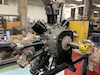
You can see the can and the contacts: G - sender (Geber) and WK - warning contact (Warnung Kontakt). Notice how the cables are soldered through them.
Here is a better view of the rheostat and the fallen screw:
Rating: 0-5 bar (G) and 0.25 bar (WK)
And here is how the mechanism for the sensor works: the pressure on the input (bottom bolt, pierced with a small hole) lifts a cylinder, with then pushes a screw that operates the rheostat. You can see it around the middle left of the image: it's the screw with the end shaped like a ball. The rheostat's arm moves along the length of the coiled wire (the resistance) and returns a resistance value proportional to the applied pressure. The gauge, which is matched to the sensor then converts this resistance to a voltage, which in turn displays the readable units on the gauge's needle.
Here you can see the warning contact: it moves together with the rheostat's arm. It's essentially a normally closed switch: if there is enough pressure (above 0.25 bar), the warning contact wiper goes past the contact and the switch is open. If the pressure falls below 0.25 bar, then the wiper goes back to its initial position and the switch is closed and the oil pressure light on the dash is on.
A pretty simple and neat mechanism. Next I'll use some thread locker and put the screw back on. If I can close the can well enough, I'll go ahead and test the sensor.
_________________
'79 Westy, P22 interior, FI 2.0 l Federal, GE engine (hydraulic lifters)
Decode your M-Plate |
|
| Back to top |
|
 |
aeromech
Samba Member
Joined: January 24, 2006
Posts: 17759
Location: San Diego, California
|
| Posted: Wed Jun 14, 2017 1:31 pm Post subject: Re: Inside the oil pressure sensor |
|
|
Good info. Thanks for doing that.
_________________
Lead Mechanic: San Diego Air and Space Museum
Licensed Airframe and Powerplant Mechanic
Licensed Pilot (Single engine Land)
Boeing 727,737-200-300-400,757,767
Airbus A319,320,321
DC9/MD80
BAe146
Fokker F28/F100
VW type 1 1962,63,65,69,72
VW Type 2 1971 (3 ea.) 1978, 1969
VW Jetta
VW Passat
Capable of leaping tall buildings in a single bound |
|
| Back to top |
|
|
aerosurfer
Samba Member

Joined: March 25, 2012
Posts: 1603
Location: Indianapolis, IN
|
| Posted: Wed Jun 14, 2017 1:34 pm Post subject: Re: Inside the oil pressure sensor |
|
|
Very cool indeed
_________________
Rebuild your own FI Harness..My Harness
77 Westy 2.0L Rockin and Rolling Resto!
72 Sportsmobile (sold)
79 Tran$porter... Parts car money machine (gone) |
|
| Back to top |
|
|
raygreenwood
Samba Member
Joined: November 24, 2008
Posts: 23526
Location: Oklahoma City
|
| Posted: Wed Jun 14, 2017 3:03 pm Post subject: Re: Inside the oil pressure sensor |
|
|
Nice! I have used quite a few of those mainly on the water cooled engines they usually came with. Never been inside one. Thank you!
Ray |
|
| Back to top |
|
|
|


