Butters56
Samba Member
Joined: April 03, 2022
Posts: 6

|
 Posted: Thu May 22, 2025 2:27 pm Post subject: 1974 Super Beetle Fuse Panel Posted: Thu May 22, 2025 2:27 pm Post subject: 1974 Super Beetle Fuse Panel |
 |
|
| Does anyone happen to have a good quality photo of the wiring going into/out of the 1974 Super fuse panel? I’m trying to re-attack and get my super running, but I gave up 2 years ago because the wiring wasn’t right, and I’ve been busy with starting my new career. So, it’s time to get her going. |
|
ashman40
Samba Member

Joined: February 16, 2007
Posts: 16485
Location: North Florida, USA

|
 Posted: Thu May 22, 2025 3:17 pm Post subject: Re: 1974 Super Beetle Fuse Panel Posted: Thu May 22, 2025 3:17 pm Post subject: Re: 1974 Super Beetle Fuse Panel |
 |
|
Here's a thread of someone with a '74 SB who posted lots of pics of their fuse box. I'm not sure pic will help you. The wiring is so compact it is hard to see everything even with a few pics.
https://www.thesamba.com/vw/forum/viewtopic.php?t=648551
Here are some tips to remember as you wire your '74 fuse box:
1) Looking at the male terminals on the fuse box, there are two rows (I know it can look like 3 rows). The row where brass bars connect pairs of fuses together is the INPUT side/row. The other row of terminals is the OUTPUT side/row. The OUTPUT side is protected by the fuse (remove the fuse and the OUTPUT side is no longer powered).
2) A single powered wire connects to the INPUT side and powers 1 or more fuses. Fuse #3-#4 are low beam fuses powered by a single yellow wire coming from the headlight dimmer relay. This wire connects to the side of the fuse with the brass bar so the one wire can power both fuses. The yellow wires connected to the OUTPUT side run to the headlights. This principle applies to all the fuses.
3) Some OUTPUT wires are connected to the INPUT side of the fuse. This is by design. Not all cicuits are protected by a fuse from the factory. For example, the black #15 ignition wire coming from the ignition switch powers fuses #11-#12 via a brass bar connecting both fuses. A second black wire connects to the brass bar. This wire runs all the way to the engine compartment to power the ignition coil, idle cutoff solenoid, choke and reverse lights. This wire is NOT protected by the fuses in the fuse box. OUTPUT wires connect to the INPUT side of fuses #9 and #10.
4) The fuse box can be broken down into 6 sections:
Parking lights : Fuse #1 + #2 (grey wires)
Low Beams : Fuse #3 + #4 (yellow wires)
High Beams : Fuse #5 + #6 (white wires)
Battery (constant) powered : Fuse #8 & #9 (red wires)
Non-Critical ignition switched : Fuse #10 (black/yellow wires)
Ignition switched : Fuse #1 + #12 (black or green wires)
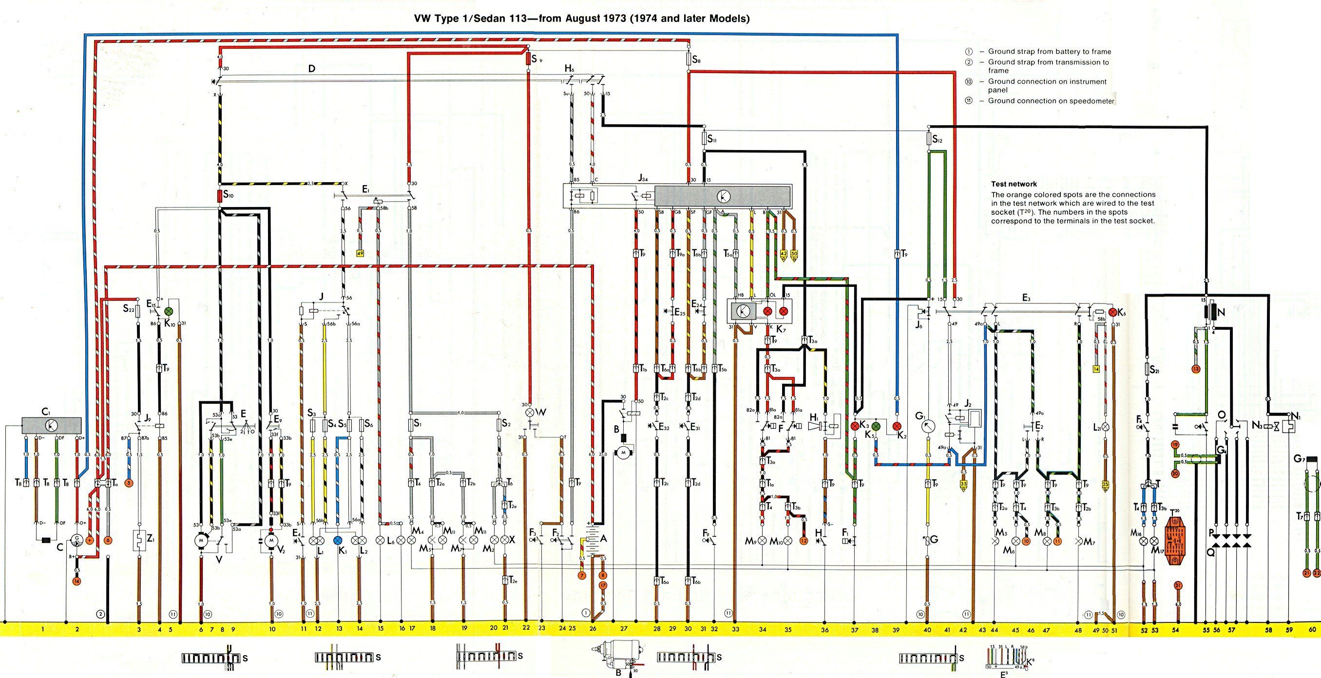
Here is the link to your '74 SB wiring diagram:

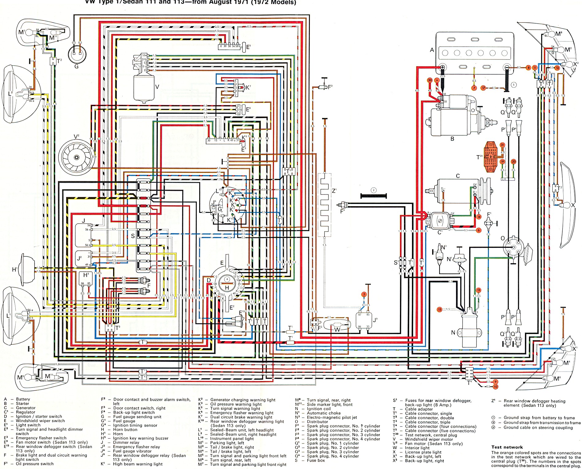
If you find that diagram too difficult, you can resort to the '72 SB diagram. The wiring at the fuse box is 90% the same.

I know the above two diagrams look completely different, but when you dive down to view how the different devices are interconnected, the two diagrams are nearly identical. The '74 one may have a few more devices as it is a newer car.
The '74 wiring diagram (top) separates circuits into a top-down orientation where in most cases 12v+ power is applied at the top of the diagram and flow down to chassis ground at the bottom of the diragram. This means the device that is being powered is typically below the switch or power source that provides it power. Even if the switch is physically located at the opposite end of the car. This makes it easy to trace the flow of current but requires you to know where in the car the device or switch is phyically located. Devices with multiple functions (turn signal switch and dimmer switch) can be located at different ends of the diagram.
The (bottom) '72 diagram tries to place everything about where it physically is on the car. The front of the car is at the left and the rear of the car to the right. The result is many wire circuits need to criss-cross over each other and switches that are physically close together are hard to see. For example, the ignition switch (D), horn button (H), turn signal switch (E2) and windshield wiper switch (E) are all clumped together at the steering column and you cannot see how the current flows thru the circuits. This is terrible for troubleshooting circuit problems because you cannot see how the circuits flows thru a device, but works good for just finding things and plugging the wires into the numbered terminal.
One big question is whether you plan to run the J34 seatbelt interconnect relay in the middle of the wiring diagram, or not. Note how may circuits pass thru this one relay. If you are planning to not use the relay, you might consider using the '73 or '75 wiring diagram where VW didn't use this relay.
_________________
AshMan40
---------------------------
'67 Beetle #1 {project car that never made it to the road  } }
'75 Beetle 1200LS (RHD Japan model) {junked due to frame rot}
'67 Beetle #2 {2019 project car - Wish me luck!} |
|

