| Author |
Message |
furgo
Samba Member

Joined: September 06, 2016
Posts: 944
Location: Southern Germany

|
 Posted: Wed Dec 06, 2017 1:55 am Post subject: L-Jetronic ECU connector pinout Posted: Wed Dec 06, 2017 1:55 am Post subject: L-Jetronic ECU connector pinout |
 |
|
I've been diagnosing and testing the fuel injection again, and I thought it'd be time to finally finish off the diagram I created a while ago, which I have been using as a reference for my '79 bus.
While researching on each input/output/power signal, I've come across a few that are specific to particular model years only (or California variant).
I first put all signals combinations on one master diagram, but I thought it would be easier to use separate diagrams with only the relevant signals for each year. I'm providing the two versions. Pick what you need (or what you like).
I've got a few signals that I could not work out, as I don't have access to the ECU of the relevant years. I've marked these in red as "TBD". In particular:
• '75-'76, '79 CA bus diagram: the full throttle (or WOT), two-pole switch has one side connected to pin 3, which is the actual input to the ECU. I don't know which voltage is applied to the other side on pin 18. It might be open, 0V or +12 V. Judging by the high altitude switch applying +12 V when closed, I guess that it's +12 V, but I don't actually know. Update: looking at the D-Jetronic ECU schematics, the other pole of the switch might actually be GND.
• '79 CA bus diagram: on pin 28, I believe there needs to be GND for the fuel pump to be properly powered, but again, I don't know without having checked the actual connection on a '79 CA ECU.
• Update– All diagrams: I noticed that on my bus the pin 20 connection (Fuel pump running) is actually N.C. on the ECU side, even though the harness has the wire coming into it. This means the ECU does not actually use that signal on a '79 bus (it neither does on a '75). It would be good to confirm if that's the case for all other years. I'll update the '77-'79 diagram with this finding later on.
I'm all set with the diagram for my own bus ('77-'79). If someone happens to want to help others to complete these other years' diagrams and measure what these signals actually are, I'd be happy to update the diagrams with the results.
I've classified each diagram grouping the changes I saw belonging to each year. I'm not sure if separate pinouts were necessary for pre-'79 CA buses, though.
Other than that, as usual, feedback and corrections will be greatly appreciated.
Thanks!
_________________
'79 Westy, P22 interior, FI 2.0 l Federal, GE engine (hydraulic lifters)
Decode your M-Plate
Last edited by furgo on Wed Dec 06, 2017 6:24 am; edited 2 times in total |
|
| Back to top |
|
 |
aerosurfer
Samba Member
Joined: March 25, 2012
Posts: 1603
Location: Indianapolis, IN
|
| Posted: Wed Dec 06, 2017 3:52 am Post subject: Re: L-Jetronic ECU connector pinout |
|
|
Nice graphic indeed. I would add to each of the years the associated ECU part number. It has been discussed, that they are interchangeable, but for anyone searching what they might need or have, we all know that year of the bus means little compared to what’s actually presently in there. Like your discussion about AFM part numbers in the other thread, the differences between ECUs may be nominal for tracking what came with what model year, but it gives clarity to the user.
From Ratwell
http://ratwell.com/technical/FISwap.html
ECU parts numbers:
Model Year
California Manual California Automatic Federal Manual Federal Automatic
1974 n/a 022-906-021K n/a
1975 022-906-021L 022-906-021M 022-906-021H 022-906-021J
1976 022-906-021Q 022-906-021R 022-906-021N 022-906-021P
1977 022-906-021AA 022-906-021AB 022-906-021S 022-906-021T
1978 022-906-021AE 022-906-021AF 022-906-021AG 022-906-021AH
1979 039-906-021D 039-906-021E 039-906-021B 039-906-021C
Vanagon 071-906-021B 039-906-021E 039-906-021C
_________________
Rebuild your own FI Harness..My Harness
77 Westy 2.0L Rockin and Rolling Resto!
72 Sportsmobile (sold)
79 Tran$porter... Parts car money machine (gone) |
|
| Back to top |
|
|
furgo
Samba Member
Joined: September 06, 2016
Posts: 944
Location: Southern Germany
|
| Posted: Wed Dec 06, 2017 5:35 am Post subject: Re: L-Jetronic ECU connector pinout |
|
|
Good call, thanks. Adding ECU part numbers instead of model year would make the diagrams more useful indeed.
The challenge I've got here is that I don't have access to or info on any ECUs other than my spare one.
I could do an educated guess at assigning ECU part numbers to the diagrams if:
• Someone would know the reason why there are different ECUs for automatic vs manual. It might be an obvious answer to some, but I've got 0 experience with automatic.
• Someone would know why there are pre-79 different ECUs for Federal vs. California (on 1979 it's clearly at least because of the O2 sensor)
In terms of the "TBD" pins, if folks are interested to find out what they are for their ECU, perhaps someone could step up to:
• Remove the ECU connector and check if there is a pin 20 present or not
• Measure the voltage at both ends of the full throttle switch (if there is one), with ignition key on.
• Measure the voltage at the double relay's pin 85, with ignition key on, on a '79 California bus,
_________________
'79 Westy, P22 interior, FI 2.0 l Federal, GE engine (hydraulic lifters)
Decode your M-Plate |
|
| Back to top |
|
|
aerosurfer
Samba Member
Joined: March 25, 2012
Posts: 1603
Location: Indianapolis, IN
|
| Posted: Wed Dec 06, 2017 5:52 am Post subject: Re: L-Jetronic ECU connector pinout |
|
|
I think it comes down to the Harness and the associated equipment on the motor.
I swapped my -s ECU with an -AH one when mine had issues with no change in performance even though I was not using the full throttle circuit that the earlier systems had.
If you look at the wiring diagram for the ECU and harness on page 41 of the AFC manual it makes no difference to all the federal models. 79 Cali is on page 42 With discernable differences.
https://www.thesamba.com/vw/archives/manuals/afc_f...Manual.pdf
More very good ECU and AFM info reading from long ago..... Particularly what Karl says!
https://www.thesamba.com/vw/forum/viewtopic.php?t=301261&highlight=ecu
_________________
Rebuild your own FI Harness..My Harness
77 Westy 2.0L Rockin and Rolling Resto!
72 Sportsmobile (sold)
79 Tran$porter... Parts car money machine (gone) |
|
| Back to top |
|
|
furgo
Samba Member
Joined: September 06, 2016
Posts: 944
Location: Southern Germany
|
| Posted: Wed Dec 06, 2017 6:54 am Post subject: Re: L-Jetronic ECU connector pinout |
|
|
| aerosurfer wrote: |
I think it comes down to the Harness and the associated equipment on the motor.
I swapped my -s ECU with an -AH one when mine had issues with no change in performance even though I was not using the full throttle circuit that the earlier systems had.
If you look at the wiring diagram for the ECU and harness on page 41 of the AFC manual it makes no difference to all the federal models. 79 Cali is on page 42 With discernable differences. |
That's probably the case, good point. I've been looking at the Bosch ECU parts list and there seem to be a few more part numbers for bus ECUs than in the ratwell table, which is probably based on the Karl thread you mentioned.
In terms of the main ECU differences/features and interchangeability, I've come to think it roughly boils down to:
• RPM Limiter function (interchangeable with all ECUs except '79 CA). A distributor rotor with mechanical RPM Limiter is needed if the ECU does not have the electronic function.
• Wide Open Throttle switch support (interchangeable with all ECUs except '79 CA). Not sure if there is a noticeable effect in running such an ECU without the actual WOT switch. From what you're saying, there isn't.
• Air temperature sensor support (interchangeable between '75 and early '76 ECUs). The '75 and early '76 busses AFM did not have an air temperature sensor output (TS1). The AFM can be upgraded to a 7-pin one and a later ECU can be used for replacement, but not the other way round (unless you downgrade to a 6-pin AFM).
• Lambda sensor support (only '79 CA). With the right harness to account for the different double-relay and removing the injector series resistors, it might well be that this ECU can operate in open loop without the O2 sensor, though. Probably too much of an effort to test this interchangeability option.
Or as a more plain summary:
• If you know what you're doing, all ECUs are interchangeable with either moderate or no extra effort except for '79 CA, which would require major harness modifications.
• There is no difference in manual vs. automatic from the ECU point of view.
I'm familiar with that thread, indeed a good read. Unfortunately, the pictures there seem to be the only ones of the inside of a bus ECU to be found. Here's my spare one, btw. I took the pics a while ago and some day I might write an "Inside the ECU" post with the notes I took:
1979 Federal, manual ECU: VW 039-906-021B; Bosch 0 280 000 178
_________________
'79 Westy, P22 interior, FI 2.0 l Federal, GE engine (hydraulic lifters)
Decode your M-Plate |
|
| Back to top |
|
|
Randy in Maine
Samba Member
Joined: August 03, 2003
Posts: 34890
Location: The Beach
|
| Posted: Wed Dec 06, 2017 9:02 am Post subject: Re: L-Jetronic ECU connector pinout |
|
|
I am not sure if the 79CA actually had a rev limiter in the ECU. I had a PM discussion with both Karl, Boston Bob, and Ratwell and I sort of remember that
no conclusion was actually drawn and I am not sure it even matters.
I do know that the 79CA set up (as well as the vanagons CA models) did not use a series resister as that was done inside the ECU. |
|
| Back to top |
|
|
SGKent 
Samba Member
Joined: October 30, 2007
Posts: 42643
Location: at the beach
|
| Posted: Wed Dec 06, 2017 9:41 am Post subject: Re: L-Jetronic ECU connector pinout |
|
|
for a fact the 1977 - 78 CA does have a rev limiter. Have hit it a couple times when testing the engine. It basically cuts the fuel off to the injectors so that the catalytic doesn't suffer from lean misfires. The injectors can only flow a certain amount of fuel so at some RPM they flat line, and any additional RPM goes lean. I would suspect that the 1979 and later California models do too.
_________________
"Most people don't know what they're doing, and a lot of them are really good at it." - George Carlin |
|
| Back to top |
|
|
Wildthings
Samba Member
Joined: March 13, 2005
Posts: 52393
|
| Posted: Wed Dec 06, 2017 10:27 am Post subject: Re: L-Jetronic ECU connector pinout |
|
|
Great idea, thanks for the effort you have put into this.
I would suggest using standard VW wire colors where possible:.
Brown for grounds
Black (or dark gray) for the switched ignition circuit (#15) (Not sure this is actually ever used on a Bus ECU)
Red for the B+ constant 12V circuit (#30) and for power coming to the ECU via the double relay. |
|
| Back to top |
|
|
furgo
Samba Member
Joined: September 06, 2016
Posts: 944
Location: Southern Germany
|
| Posted: Wed Dec 06, 2017 11:47 am Post subject: Re: L-Jetronic ECU connector pinout |
|
|
| Wildthings wrote: |
I would suggest using standard VW wire colors where possible:
Brown for grounds
Black (or dark gray) for the switched ignition circuit (#15) (Not sure this is actually ever used on a Bus ECU)
Red for the B+ constant 12V circuit (#30) and for power coming to the ECU via the double relay. |
Good point, thanks for the feedback!
Even though all ECU wires were white, I can use the brown and red color coding at least. The sensor inputs I'll keep color-coded in yellow, as it's more visible than white.
_________________
'79 Westy, P22 interior, FI 2.0 l Federal, GE engine (hydraulic lifters)
Decode your M-Plate |
|
| Back to top |
|
|
furgo
Samba Member
Joined: September 06, 2016
Posts: 944
Location: Southern Germany
|
| Posted: Wed Dec 06, 2017 11:52 am Post subject: Re: L-Jetronic ECU connector pinout |
|
|
I've correlated the VW part numbers with the Bosch part numbers to get some more information from the Bosch ECU parts list. I translated the part descriptions and then added them to the original table.
Some things to notice:
• The Bosch documentation is not very consistent in describing which functions an ECU part # had. Also some key capabilities such as injector current control of the '79 CA ECUs were never listed.
• There were separate part numbers for ECUs going to the Swedish market too.
• From the descriptions, some degree of interchangeability can already be inferred.
• The first ever Type 2 ECU (1975, CA Manual) seemed to have all available functions except for Lambda control (which had not yet been on the market). Subsequent ECU parts removed or added functions as necessary. This lead to an explosion of part numbers, but it must have been cost-effective enough to justify it. There are even more ECU part numbers in the Bosch parts list, but I've focused only on the known ones from the original Karl table.
• I've translated the different ECU functions from some other Bosch document. They're described below.
• Being quite honest, I don't quite understand what the anti-bucking (Anti-Ruckeln in German) circuitry does, but it seems to have been an internal circuit in the ECU that acted upon particular changes of air flow and engine speed.
• A couple of ECUs have acceleration enrichment capability. I don't know how acceleration was sensed, unless a throttle position sensor (instead of the WOT switch) such as the D-Jetronic one was used. The ECU could have sensed the rate of speed change, but there were limits to what a bunch of discrete components could do, this was not a microcontroller-based ECU.
Full load enrichment – when a full load event is detected via the Wide Open Throttle (WOT) switch, the injector time is extended to enrich the mixture (WOT switch, ECU).
RPM limiter – fuel injector pulses are stopped at engine speed values higher than 5400 RPM (ECU).
Intake air correction – In order to compensate for the physically induced measuring error of the air flow meter, the injection time is corrected as a function of the intake air (Air flow, TS1, ECU)
Acceleration enrichment – Upon acceleration with the gas pedal, a temperature- and time-controlled fuel enrichment takes place (TS2, ECU)
Post-start enrichment – After the motor has started, an additional quantity of fuel will be injected as means of enrichment, that will be dependent on time and engine temperature (TS2, ECU).
Anti-bucking – When bucking occurs, it is assumed that the load changes are smaller than in an intended acceleration. If a load change occurs below a certain threshold value, the control variable will not be the newly calculated value of the slightly changed load, but instead it will be an approximation of this new value (Air flow, engine RPM, ECU).
_________________
'79 Westy, P22 interior, FI 2.0 l Federal, GE engine (hydraulic lifters)
Decode your M-Plate |
|
| Back to top |
|
|
SGKent
Samba Member
Joined: October 30, 2007
Posts: 42643
Location: at the beach
|
| Posted: Wed Dec 06, 2017 12:59 pm Post subject: Re: L-Jetronic ECU connector pinout |
|
|
the ECU is analog. It is not a computer with software programming. It takes the square/sawtooth wave generated the coil primary, shapes and amplifies it then uses that to open and close the injectors. All other sensors add time to the period the injectors are open depending on what the sensor sends to the ECU. The only smart logic it has in a sense is to know which way the AFM door is swinging and how fast. That is how later models know to add extra fuel for acceleration.
_________________
"Most people don't know what they're doing, and a lot of them are really good at it." - George Carlin |
|
| Back to top |
|
|
airkooledchris
Samba Member
Joined: January 25, 2005
Posts: 2720
|
| Posted: Thu Dec 07, 2017 11:49 am Post subject: Re: L-Jetronic ECU connector pinout |
|
|
| SGKent wrote: |
| for a fact the 1977 - 78 CA does have a rev limiter. Have hit it a couple times when testing the engine. It basically cuts the fuel off to the injectors so that the catalytic doesn't suffer from lean misfires. The injectors can only flow a certain amount of fuel so at some RPM they flat line, and any additional RPM goes lean. I would suspect that the 1979 and later California models do too. |
the 79 absolutely does. Colin and I stumbled upon this when my gas pedal stuck to the floor and the engine started banging up against the limiter like an angry race car. we quickly killed the ignition and corrected the issue, but it was a definite confirmation. I want to say it was somewhere around the 5K mark. |
|
| Back to top |
|
|
ve7kilohertz
Samba Member
Joined: June 28, 2015
Posts: 163
Location: Okanagan BC
|
| Posted: Thu Jun 07, 2018 10:24 am Post subject: Re: L-Jetronic ECU connector pinout |
|
|
Hi Furgo et al,
Are you still working on this project? I may be able to contribute to your research as I am piecing together a L-Jet system for a 1.6 or 1.7L engine. I have 2 ECUs from buses, both I have apart to see what differences there are, 022 906 021AG and 022 906 021S. I also am working on figuring out differences in AFM's over the '76-'83 years. I have a couple of each of 6 pin and 7 pin, '76, '78 and '83. 006 012 and 030.
Cheers |
|
| Back to top |
|
|
furgo
Samba Member
Joined: September 06, 2016
Posts: 944
Location: Southern Germany
|
| Posted: Thu Jun 07, 2018 2:24 pm Post subject: Re: L-Jetronic ECU connector pinout |
|
|
Hey,
thanks for the offer. While I'm currently not actively working on this, having some pictures of other ECUs would definitely be interesting.
Other than that, the same unanswered questions of the first post remain. To recap:
• Pin 18: is it +12V? Need either '75, '76 or '79 CA ECU (or bus) with WOT switch to confirm.
• Pin 20: is the "fuel pump running" signal unused (i.e. open pin or no pin present on the ECU connector) only on '79 Federal ECUs or on all years?
• Pin 28: is it permanent GND? Need '79 CA ECU/bus to confirm.
If someone with that configuration could contribute, then the pinout diagrams would be complete.
Looking them up on the table your ECUs seem to be:
022 906 021 AG - Federal manual '78
Model 78 Sweden, same as 022 906 021 A (Model 77 California, with RPM limiter), but with acceleration enrichment
022 906 021 S - Federal manual '77
Model 77 USA, without full throttle correction
_________________
'79 Westy, P22 interior, FI 2.0 l Federal, GE engine (hydraulic lifters)
Decode your M-Plate |
|
| Back to top |
|
|
Tcash
Samba Member
Joined: July 20, 2011
Posts: 12846
Location: San Jose, California, USA
|
| Posted: Thu Jun 07, 2018 2:59 pm Post subject: Re: L-Jetronic ECU connector pinout |
|
|
| onion456 wrote: |
heres a few more, probably raped from ratwells, ive found em useful.
85 - Ground
86 - Thermo time switch and ECU pin 4
86a - Starter
86b - AFM harness connector #36
86c - Terminal 15 of ignition coil (+12v)
88a - AFM harness connector #39
88b - Series resistors and ECU pin 10
88c - Aux air regulator
88d - Fuel Pump
88y - Battery +12v
88z - Battery +12v
|
|
|
| Back to top |
|
|
ve7kilohertz
Samba Member
Joined: June 28, 2015
Posts: 163
Location: Okanagan BC
|
| Posted: Fri Jun 08, 2018 8:00 am Post subject: Re: L-Jetronic ECU connector pinout |
|
|
Tcash,
Excellent info and drawings, explains a lot and is very helpful. Thanks! Where did you find this info? I have been looking on line for a while now and have not seen some of these drawings.
Cheers |
|
| Back to top |
|
|
ve7kilohertz
Samba Member
Joined: June 28, 2015
Posts: 163
Location: Okanagan BC
|
| Posted: Fri Jun 08, 2018 8:33 am Post subject: Re: L-Jetronic ECU connector pinout |
|
|
Here are the 2 ECUs I have. Let me know if there is anything else you want pictures of. Cheers
|
|
| Back to top |
|
|
furgo
Samba Member
Joined: September 06, 2016
Posts: 944
Location: Southern Germany
|
| Posted: Fri Jun 08, 2018 10:35 am Post subject: Re: L-Jetronic ECU connector pinout |
|
|
| ve7kilohertz wrote: |
| Here are the 2 ECUs I have. Let me know if there is anything else you want pictures of. |
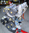
Excellent, thanks! Perhaps not a picture, but would you be able to just tell me the printed part marking on the one power transistors placed at the side of each board's frame? The one on my ECU refers to an obsolete part, for which there isn't even a datasheet. I'm thinking there were equivalent transistors being used throughout the years. I'm simply curious to see if their specs can be found.
What I see at a first glance from your 2 ECUs:
- The three Bosch ICs (pulse shaper + freq. divider, division control multivibrator (*), multiplier stage) seem to be a constant regardless of ECU year.
- The form factor of these in older ECUs is the "spider" type (TO... something package). Later ECUs seem to have evolved these into a small PCB in a plastic case. I assume to cram more functionality into them as new ECU functions were required.
Here's again a picture of my spare ECU I posted a while back in an unrelated thread. I might as well add it here for comparison:
(*) a very obscure name for the IC that calculates the basic injector time from essentially the engine speed and AFM output signals.
_________________
'79 Westy, P22 interior, FI 2.0 l Federal, GE engine (hydraulic lifters)
Decode your M-Plate |
|
| Back to top |
|
|
Tcash
Samba Member
Joined: July 20, 2011
Posts: 12846
Location: San Jose, California, USA
|
| Posted: Fri Jun 08, 2018 12:39 pm Post subject: Re: L-Jetronic ECU connector pinout |
|
|
| ve7kilohertz wrote: |
Tcash,
Excellent info and drawings, explains a lot and is very helpful. Thanks! Where did you find this info? I have been looking on line for a while now and have not seen some of these drawings.
Cheers |
Diagrams
Fuel Injection Diagrams Collection FAQ
Gallery search |
|
| Back to top |
|
|
ve7kilohertz
Samba Member
Joined: June 28, 2015
Posts: 163
Location: Okanagan BC
|
| Posted: Sun Jun 10, 2018 8:47 am Post subject: Re: L-Jetronic ECU connector pinout |
|
|
Thanks for the picture, looks completely different with more modern ICs.
TO-3 power transistor is ON503, 7637 is the date code. The IC's in mine are TO-5 package, I suppose I could pull the heat sinks to get the part numbers but as they are proprietary, probably no point. Hopefully these ECUs work, one was marked NFG, but after close examination of the traces on the bottom, I found a couple of solder bridges between wires passed thru from the top side, and pads. Not sure if that was an intentional connection or not. ?? Pretty poor QC in my opinion if they are not supposed to be joined. Would be good to find another similar ECU type to compare. Here is a picture of what I am referring to. In the top side photo, you can see the wires soldered and passed thru to the bottom layer, 2 of them were "joined" to pads on the bottom, which looked like solder bridging, the others were all just bent over but not soldered, maybe test points? Maybe different connections for vehicle or sensor variations? I used to work in a SMT contract mfr and that's all we did, stuff thru hole and SMT circuit boards for various mfrs and I have a fair bit of experience in QCing this type of circuit board.
Thanks Tcash, that is an impressive collection of data! Hadn't seen that post before.
Cheers
|
|
| Back to top |
|
|
|


