| Author |
Message |
70bus
Samba Member
Joined: July 15, 2004
Posts: 1465
Location: P.O.

|
 Posted: Sun Apr 13, 2025 1:43 pm Post subject: 63 - 65 US spec turn signal emergency flasher tester Posted: Sun Apr 13, 2025 1:43 pm Post subject: 63 - 65 US spec turn signal emergency flasher tester |
 |
|
Despite their age - and sometimes because of it - VWs still hold mysteries. Even after decades of the internet in general and thesamba in particular, we still find questions to toss at fellow owners. I’m going to focus on a few, like, “what is this knob” or “why don’t my turn signals work?” or “this light won’t turn off when key is off.”
Some of you may have noticed that I am -ahem- a tad obsessed about the turn signal/hazard circuit on mid-60s US-spec buses. I am fascinated that despite several hundred posts about them
https://www.thesamba.com/vw/forum/search.php?searc...=titleonly
https://www.thesamba.com/vw/forum/search.php?searc...=titleonly
https://www.thesamba.com/vw/forum/search.php?searc...=titleonly
https://www.thesamba.com/vw/forum/search.php?searc...=titleonly
we can not always find consensus on what the issue is, let alone a consistent solution. Some people have the exact same problem for which a successful solution was posted, yet that solution does not work for them.
One issue in troubleshooting is that it is a hassle; kick panels have to come off, things carefully peered at behind dash, wires traced, parts tested. Sometimes if the issue is minor it gets lived with; an intractable large issue can result in reliability issues and major frustration. So I decided to make a test rig.
The BusInABox, a 63 - 65 flasher/hazards tester
The original idea was use parts on hand, which I mostly did. I did need a donor speedo with the proper indicator light, and a 6-wire turn signal switch, as I didn’t want to resolder the melted wires on my truck’s original unit. The NoName Garage in Eugene and Always-V-Dub here in Portland provided them for cheap or free; many thanks.
A bench-top proof of concept:
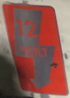
A $5 Habitat ReStore toolbox provides the case. Anyone recognize the logo?
Mocking up placements on cardboard and then my former bolt-sorting cookie sheet
which wasn’t strong enough to stay unwiggly, so I dug out my huge-ass piece of .050 copper sheet. I don’t even want to know what it would cost now. Good news is I could still cut it with hand tools, though I did have to buy a new hole saw for the speedometer. I also bought some Pomona banana- plug components, because of course I didn’t have enough. The object of the bananas is to allow ANY relay to be tested, without messing with tight or loose terminal connectors, constant opening of the test box to swap them out, or worrying if they will fit. Alligator clips on the other end of test leads for similar reasons.
Home-made latch
Started with these bulb holders, but they are junk, esp the newer ones. The 1158-bulb holders were just asking for shorts. They also needed extra space in the mounting hole sides to allow the bulge for seating pins to pass, making them loose in the dash, and they also often were tapered at bulb end; this made it impossible to keep them in one place, despite many efforts. Considered soldering them in, but they were so craptacular I didn’t relish replacing them if needed. You'll see them in some shots before I gave up and went with these taller ones, even tho they don’t look as cool in use.
Mounting the t/s switch involved a piece of wood from my deck and some washers; it will move a bit if you don't hold it, so as stock.
A quick spritz of L87 and Bob's yer uncle.
For power, I had 12v and 6v batteries with 8A; I used the 12v to test my truck wiring, so I know it can handle the load - my 30V5A bench supply could not, which was one of my motivations for building this silly thing. I wanted to have the unit be entirely self-contained, but the size of the batteries, the brackets in the toolbox, and the parts hanging from the ‘dash’ meant too little room. I considered having a separate ‘hot’ plug for 6 and 12v batts, but decided to go with an internal 12v/6v reducer; this also allows me to just take the rig anywhere that had a 12v supply, or not haul two batteries around. Drop unit has its issues, but seems to be working. Yes, things have been bolted down since this pic.
Here is the wiring setup:
Power comes in leads through side of case; 8A fuse on hot. Neg goes to a ground bar, hot goes to center terminal on one side of a DPDT switch; switch goes to a 4A circuit breaker and then to a power strip. When 6v is selected, power is fed to the voltage drop and then to the other side of the DPDT, and then to circuit breaker. Power strip has connections for an ‘ignition key on’ circuit, with its own breaker. None of this should have anything to do with the operation of the tester - this is just like the battery in our VWs going to the fuse box - but I detail it just in case someone sees an issue down the line.
The ‘always hot’ strip is a stand in for fuse #1, and has connections straight to the + on the t/s relay, and to the indictor bulb in the speedo; technically, it feeds what’s normally the ‘ground’ side of the bulb holder, but in our case is hot. The ‘IGN’ side is fuse #2, and I may not have it set up correctly for testing so feel free to correct it; for our tests, it serves two purposes: primarily, it acts as the ‘key on’ feed to the light cluster at bottom of the speedo. This is where the indicator light gets its power from when using a relay that has no K, just 49+. The secondary purpose is to connect to the brake switch; more on this later.
After that, the wiring is exactly as it is on the 63-by-owner diagram
https://www.thesamba.com/vw/archives/info/wiring/bus_63_USA_with_emergency.jpg
An aside: I have a few factory manuals, and they all show the wiring for the indicator light like this one
https://www.thesamba.com/vw/archives/info/wiring/bus_63_USA.jpg
These are all published after 67 as far as I can tell. My 63-up manuals were published by VW in 1968 and 1970, for example. I also note that the second setup is alleged to cause some problems this device is made to test. I would love to see a FACTORY wiring diagram published before 1966. After 66, it makes sense that they printed what went with the parts VW was then providing... except that they still show the t/s relay with K + and S instead of 49, 49a and 31! I trust that the number of bus owners who report their VWs are wired per the first diagram means it is likely correct in general, but it is curious why VW seemingly never made an official diagram of that layout and put it in a shop manual.
Enough about construction; let's get testing!
First, let's make sure the turn signal circuit is working; this is wired with indicator light from an 'always on' source for this test, and no emergency relay. I only have one 6v bulb right now, so I'm using 12v here, and an early bay t/s box. These boxes were the way to solve flasher issues in these buses for many years; I will also be testing a modern version compatible with LEDs. If I ever find the stock M620/M621 relay I'll test it, but that's been a 4-year search with no results.
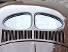
Lights and speedo indicator work properly! Please note sometimes my camera doesn't always catch the lights properly, especially the indicator and dash hazard. I'll post better images as I go.
Since one of the tasks for this unit is to look for unexpected weirdness, to look for odd crossover or backcurrents, I pulled the emergency knob and the rear flashers started up! I could activate the turn signal switch, and the rear flashers AND the front side selected would flash.
At first this seemed odd, but talking it over with BarryL (who has provided a lot of advice on these buses for me) it makes sense - the missing emergency relay only serves to add the fronts to the rears, so the t/s circuit does the rears, regardless of what's going on elsewhere. So a result already: if you are getting rear hazards but not front, find out why your emergency flasher relay isn't working. For starters, make sure it isn't a headlight relay, which looks the same and is same place !
Emergency flasher part numbers - 6v, 211 953 191. 12v, 211 953 207.
Now let's check the hazards. Hazards work fine; note that the indicator light flashes IN TIME with the turn signal bulbs, as does the dash light for the hazards. I need to get a better angle to catch the dash light as I could only find a 14v bulb. Gonna be real faint in 6v tests...
A final test; remember the circuit from brake switch to fuse 2? This pushbutton stands in for our brakes, and this light represents our coil. An oddity of this system is that when your motor is running, the flashers are going, you step on the brakes and THEN turn off the key... the motor will restart, stop, and restart in time with the flashers as long as you have brakes on! This is because current is backfeeding through the brake switch, to fuse 2, and back to the coil. Releasing brakes breaks the circuit and motor stays stopped.
So everything seems to work as it should if you have a bus wired per the '63 with e-flashers' diagrams.
So, AS FAR AS I CAN TELL, the tester duplicates the emergency/turn-signal setup on US-spec buses from 63 to 65. Any later or earlier examples? Also, please comment on anything yu see that seems off, whether construction, theory, or kust me in general for doing this.
Next step will be testing it with 6 volt parts, and then testing the dozens of relays I have accumulated. One goal is to see which ones you could use if you run across them, and which ones will not work.
_________________
Craig K
70 Neunsitzer
65 Pritschenwagen
"If Von Dutch was alive, he'd walk in there with a pistol and shoot these people." - Robert Williams
Raul the 65 singlecab
Karl the 70 nine-seater
Last edited by 70bus on Sun Apr 13, 2025 7:26 pm; edited 2 times in total |
|
| Back to top |
|
 |
Eric&Barb
Samba Member
Joined: September 19, 2004
Posts: 26092
Location: Olympia Wash Rinse & Repeat
|
| Posted: Sun Apr 13, 2025 2:39 pm Post subject: Re: 63 - 65 US spec turn signal emergency flasher tester |
|
|
Nice work! Will be on the edge of our seats for what you find.
_________________
In Stereo, Where Available! |
|
| Back to top |
|
|
70bus
Samba Member
Joined: July 15, 2004
Posts: 1465
Location: P.O.
|
| Posted: Sun Apr 13, 2025 5:00 pm Post subject: Re: 63 - 65 US spec turn signal emergency flasher tester |
|
|
Tested a few 12v t/s relays, some with proper K terminals and others with 49a.
On the test rig, the wire colors are the same as you would find under the dash... although my donor t/s switch had gotten warm enough to melt some colors onto other wires, so not as obvious as they could be. More real-life variables, simulated! Anyways, that's why the leads are also tagged. If a wire is doubled at a terminal, and you just see one wire here, rest assured the pair is under the dash; the leads are just extending the terminal tabs, essentially. We're using an early bay 211953215c box.


Works as advertised; note that the indicator bulb source switch is set to

which means it is wired to fuse #1 AND the K on the t/s relay.

It works as it should; note that the indicator light flashes IN TIME with the signal bulbs. If I set the indicator source to off, it obviosuly doesn't light. Flipping the switch to 'external' makes it work, even with the IGN circuit off. Not sure if that is how it should be, honestly.
Pulling the emergency knob w/ no hazard relay yields the proper result: rears flash, not fronts. Indicator and dash light comes on if t/s relay is in good working order. Sometimes the indicator doesn't always work in this scenario if weak relay.

Using the t/s stalk get the front for that side added.

Let's add the emergency/hazards relay. It all works as expected; an interesting effect is trying to use t/s switch when hazards are on - they all light, but stop flashing.
Neither BarryL nor I have left them like this for any length of time to see what happens. VW obviously didn't think you'd do this, but I can see if you bump the stalk, or signal to pull over, hit the hazards, and forget the stalk is selecting a side, you may be puzzled as to what's going on. Now you know. Let us know if this happens to you, and how long it can go on before something 'interesting' happens... and what that interesting thing is.
Next let's try what is a common replacement type for the original t/s relay

31, 49, 49a; K goes on 49a. For this, I have set the rig up as per the typical wiring diagrams that show indicator bulb gettiing power from speedo cluster, and ign circuit on. Works, with a quirk:


The indicator bulb works OPPOSITE the signal bulbs. Why?
A few posts explain this but ashman40 was thorough when they wrote:
"I took a shot at diagramming how the corner turn signal lights (on one side) and the speedometer indicator lamp work opposite each other. When the flasher relay powers the corner lamps it causes the indicator lamp to go out. When the flasher relay pulses OFF, it allows the indicator lamp current to flow.
I'm hoping this does a good job explaining why the turn indicator lamp light turns ON when the corner lamps pulse OFF and why the turn indicator lamp turns OFF when the corner lights pulse ON.
The size of the arrows tries to illustrate high current (high wattage) flow vs. low current (low wattage) flow.
Here are a few principles to keep in mind as you view the diagram:
A 2W bulb acts as a restriction in the circuit limiting the current flow to just 2W. Anything downstream that is expecting more wattage may not operate as expected (does not turn ON).
Sufficient current flow thru a bulb causes the bulb to light up. Less current flow and the bulb may glow instead of fully lighting up. Insufficient current flow and the bulb does not turn ON at all even if a small amount of current is flowing thru the bulb.
Similar levels of positive voltage on both terminals of a bulb results in no current flow thru the bulb (even if there is potential/voltage present at the bulb) and the bulb will remain OFF. Current flow depends on a different voltage potential in the circuit.
Below you can see when the flasher relay 49a powers the corner lamps with a high watt source it also results in no current flow thru the speedometer turn indicator lamp; resulting in the indicator lamp turning OFF.
In the below diagram you can see the flasher relay 49a has pulsed OFF. Lacking the current flow out of 49a the current coming from the fuse flows thru the 2W indicator lamp. But since the indicator lamp is only 2W the flow thru the corner lights is much smaller (1/25th of the output of the flasher relay). The flow is so small there is not enough current to get the two 25W corner lights to turn ON. But since the indicator lamp is able to ground thru the corner bulbs the indicator lamp turns ON until the flasher relay next pulses ON.
Here are a few principles to keep in mind as you view the diagram:
A 2W bulb acts as a restriction in the circuit limiting the current flow to just 2W. Anything downstream that is expecting more wattage may not operate as expected (does not turn ON).
Sufficient current flow thru a bulb causes the bulb to light up. Less current flow and the bulb may glow instead of fully lighting up. Insufficient current flow and the bulb does not turn ON at all even if a small amount of current is flowing thru the bulb.
Similar levels of positive voltage on both terminals of a bulb results in no current flow thru the bulb (even if there is potential/voltage present at the bulb) and the bulb will remain OFF. Current flow depends on a different voltage potential in the circuit.
Below you can see when the flasher relay 49a powers the corner lamps with a high watt source it also results in no current flow thru the speedometer turn indicator lamp; resulting in the indicator lamp turning OFF."
Now, this relay was also working with the indicator light set to 'ign off, normal source;' more worrying, it the indicator DID NOT light when the ign circuit was off and any source setting. This means it fails to replicate a common issue - the indicator light being on when not wanted. This can be fixed by using the Dorr Diode
"When using the turn signals, if the green indicator lights when the key is off but works correctly when the key is on, you can fix it by adding a diode (eBay, 1N400X, where X = 1 through 7, banded end connected to the flasher) in series with the indicator light. This is because the flasher has power when the key is off but the indicator does not. The diode stops current from flowing through the flasher, then through the indicator, and finally to ground via the inactive ignition circuits, but does let current flow the other way when the ignition is powered." -Telford Dorr
So until I (or you) can figure out why this isn't happening in the tester, and how to fix it, I'll stop for now.
_________________
Craig K
70 Neunsitzer
65 Pritschenwagen
"If Von Dutch was alive, he'd walk in there with a pistol and shoot these people." - Robert Williams
Raul the 65 singlecab
Karl the 70 nine-seater
Last edited by 70bus on Sun Apr 13, 2025 6:37 pm; edited 1 time in total |
|
| Back to top |
|
|
BarryL 
Samba Member

Joined: November 01, 2004
Posts: 15282
Location: Casa de Oro, California
|
| Posted: Sun Apr 13, 2025 6:34 pm Post subject: Re: 63 - 65 US spec turn signal emergency flasher tester |
|
|
| Patent it quick. |
|
| Back to top |
|
|
nlorntson
Crazy VW Lady
Joined: March 13, 2004
Posts: 3856
Location: Twin Cities, MN
|
| Posted: Sun Apr 13, 2025 8:12 pm Post subject: Re: 63 - 65 US spec turn signal emergency flasher tester |
|
|
| Really well done! |
|
| Back to top |
|
|
stevo
Samba Member

Joined: January 22, 2004
Posts: 982
Location: the eugeniverse
|
| Posted: Sun Apr 13, 2025 8:36 pm Post subject: Re: 63 - 65 US spec turn signal emergency flasher tester |
|
|
Outstanding.
I have a factory 12V Standard with the M-code plate showing it birthed April 23, 1965 with M620 & M621, along with original emergency flasher 211953207. Not certain this is the time or place, but my emergency flashers work fine in the rear though up front they will work once on the first pull and then the fronts quickly go out while the rears continue. Having checked off so many priorities [the bus was crushed]I'm nearing the bottom of the list which includes consideration of this electrical issue. So I'm looking forward to seeing this thread develop and learning how it sheds flashing light on my situation.
_________________
When you cross an Irishman, they never forget. I mean, never. |
|
| Back to top |
|
|
70bus
Samba Member
Joined: July 15, 2004
Posts: 1465
Location: P.O.
|
| Posted: Sun Apr 13, 2025 8:45 pm Post subject: Re: 63 - 65 US spec turn signal emergency flasher tester |
|
|
When you have the time, there's a very easy check for that: swap the 207 relay for any modern cube relay with 87 and 87b.
If everything works fine, then the 207 has issues; you coud take it apart, clean, and try to improve the ground connection between the can and the interior of the relay (usually a little tab on side of board the relay is mounted to).
If it doesn't fix it, hopefully this box will provide answeres some day!
PS - your bus was made about a week before mine! When running, we need to meet and compare.
_________________
Craig K
70 Neunsitzer
65 Pritschenwagen
"If Von Dutch was alive, he'd walk in there with a pistol and shoot these people." - Robert Williams
Raul the 65 singlecab
Karl the 70 nine-seater |
|
| Back to top |
|
|
mdege
Samba Member

Joined: January 16, 2018
Posts: 1066
Location: Niederkruechten, Germany
|
|
| Back to top |
|
|
70bus
Samba Member
Joined: July 15, 2004
Posts: 1465
Location: P.O.
|
| Posted: Mon Apr 14, 2025 11:14 am Post subject: Re: 63 - 65 US spec turn signal emergency flasher tester |
|
|
Yes, US buses must have hazards available at all times. That's one of the causes of t/s-emergency-indicator issues.
I do have an actual ignition switch I could use, but for the tester I just used a toggle, visible above t/s switch housing
An ignition switch basically ties 30 (always hot) to 15 (key hot) and in theory the toggle is doing the same, as it connects a pair of terminals to power when flipped. That power then goes to the indicator bulb. It is possible that there is some aspect of the circuit I'm overlooking, so happy to hear thoughts, especially why I am not getting the common fault of the indicator light on at the wrong times when using "49a" relays.
If I can find the key that goes in my spare ign switch I may patch it in to test whether the toggle really functions the same. Hell, I''ve considered putting my spare light switch in there to make sure it has no effect!
In my darkest hours I have thought of connecting the tester to my car, to see if the motor does the brake switch on/off/on thing with it.
_________________
Craig K
70 Neunsitzer
65 Pritschenwagen
"If Von Dutch was alive, he'd walk in there with a pistol and shoot these people." - Robert Williams
Raul the 65 singlecab
Karl the 70 nine-seater |
|
| Back to top |
|
|
BarryL
Samba Member
Joined: November 01, 2004
Posts: 15282
Location: Casa de Oro, California
|
| Posted: Mon Apr 14, 2025 6:34 pm Post subject: Re: 63 - 65 US spec turn signal emergency flasher tester |
|
|
On my '65 wired like your '63 Bus Owner diagram with the key off, and turn signal on, the green light is syncopated with outside lights.
With flasher on, the green light is syncopated with the outside lights and the red light is synchronized. |
|
| Back to top |
|
|
70bus
Samba Member
Joined: July 15, 2004
Posts: 1465
Location: P.O.
|
| Posted: Mon Apr 14, 2025 8:54 pm Post subject: Re: 63 - 65 US spec turn signal emergency flasher tester |
|
|
Which is how it works on all the relays I’ve tested which have the proper K behavior; the 49a ones all do the green arrows opposite to other bulbs. The mystery is why yours works, since IIRC you have a 49a t/s relay. :)
_________________
Craig K
70 Neunsitzer
65 Pritschenwagen
"If Von Dutch was alive, he'd walk in there with a pistol and shoot these people." - Robert Williams
Raul the 65 singlecab
Karl the 70 nine-seater |
|
| Back to top |
|
|
70bus
Samba Member
Joined: July 15, 2004
Posts: 1465
Location: P.O.
|
| Posted: Wed Apr 16, 2025 12:23 am Post subject: Re: 63 - 65 US spec turn signal emergency flasher tester |
|
|
A question - anyone with these buses, what happens when you have the flashers on, and you hit the brakes? On my truck, all the lights light up and stop flashing, like when you use the turn signals while flashers are on. This doesn’t happen on the tester; now I need to contemplate which is correct, if the tester is wired correctly, and is my truck!
_________________
Craig K
70 Neunsitzer
65 Pritschenwagen
"If Von Dutch was alive, he'd walk in there with a pistol and shoot these people." - Robert Williams
Raul the 65 singlecab
Karl the 70 nine-seater |
|
| Back to top |
|
|
BarryL
Samba Member
Joined: November 01, 2004
Posts: 15282
Location: Casa de Oro, California
|
| Posted: Wed Apr 16, 2025 11:02 am Post subject: Re: 63 - 65 US spec turn signal emergency flasher tester |
|
|
Key on or key off?
Key off: mine flashes twice as slow. Key on: mine flashes twice as fast; almost like it's shorting out. |
|
| Back to top |
|
|
BarryL
Samba Member
Joined: November 01, 2004
Posts: 15282
Location: Casa de Oro, California
|
| Posted: Wed Apr 16, 2025 11:04 am Post subject: Re: 63 - 65 US spec turn signal emergency flasher tester |
|
|
| 70bus wrote: |
The mystery is why yours works, since IIRC you have a 49a t/s relay.  |
Can you show photo of the 49a relay? |
|
| Back to top |
|
|
70bus
Samba Member
Joined: July 15, 2004
Posts: 1465
Location: P.O.
|
| Posted: Wed Apr 16, 2025 11:22 am Post subject: Re: 63 - 65 US spec turn signal emergency flasher tester |
|
|
EDIT - with key off, flashers on, push brake: all lights continue as normal, but my gas needle and the electronic tach needle flail back and forth in time with flashers. Gas goes nearly full travel! Need to fix that gas gauge somehow
Key on - all lights go on and stay on EXCePT indicator arrow which stays off; gauge needles stay in place in usual ign positions; proper gas level, tach at zero..
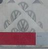
This is an image you posted saying it is from your bus
I see this can in a lot of buses posted. It obviously works for you, with quirks like 'brake on/flashers on' speeds, vs my relay with a K that locks them all on in that scenario.
One of my goals w/ this tester was to identify issues and fixes (if needed) for using your relay vs. mine. Hard to do if the tster can't match the OG system and common issues!
Since your flashers/brake result is similar to the t/s and brake result, I wonder if they are related. My tester doesn't actually connect to a coil; a possible cause of your result?
_________________
Craig K
70 Neunsitzer
65 Pritschenwagen
"If Von Dutch was alive, he'd walk in there with a pistol and shoot these people." - Robert Williams
Raul the 65 singlecab
Karl the 70 nine-seater |
|
| Back to top |
|
|
BarryL
Samba Member
Joined: November 01, 2004
Posts: 15282
Location: Casa de Oro, California
|
| Posted: Wed Apr 16, 2025 6:23 pm Post subject: Re: 63 - 65 US spec turn signal emergency flasher tester |
|
|
| 70bus wrote: |
This is an image you posted saying it is from your bus
|
I didn't know that was called a 49a relay. The photo is from an identical year 6 volt bus as mine. I'm assuming mine is the same but remember I was the guy too lazy to take off my kick panel and look for you. |
|
| Back to top |
|
|
BarryL
Samba Member
Joined: November 01, 2004
Posts: 15282
Location: Casa de Oro, California
|
| Posted: Wed Apr 16, 2025 6:25 pm Post subject: Re: 63 - 65 US spec turn signal emergency flasher tester |
|
|
| 70bus wrote: |
| My tester doesn't actually connect to a coil; a possible cause of your result? |
A coil with the points open will read like a dangling wire connected to nothing BUT THE CHOKE which is a resistor. A closed coil will act like a heavier resistor.
So you really should put something to load it. |
|
| Back to top |
|
|
70bus
Samba Member
Joined: July 15, 2004
Posts: 1465
Location: P.O.
|
| Posted: Wed Apr 16, 2025 6:55 pm Post subject: Re: 63 - 65 US spec turn signal emergency flasher tester |
|
|
Well, I call them "49a relays," to differentiate them from relays with a K (or P, or C). It is properly called whatever part number VW or Hella or Bosch or Webasto or SWF or... calls it.
I doubt anyone but me calls them 49a, but it is faster than saying 'Bosch 0 336 256 002 does not have a K terminal, but has 49a to indicator bulb.'
On the coil load - the tester has a 12v bulb to imitate the coil, so not loadless, but should I put something else on it?
I'm a little alarmed that the brakes/flashers/key off affects my gas gauge like if does; as I am having an OG M620 12v gauge restored, the last thing I want to do is fry it. It is NOT conected to the indicator bulb, as it would be if using the wiring which uses key-on circuit to power indicator bulb. The effect is sort of like testing a gas gauge for being "good:" touch a hot wire to the + sign and see if needle goes hard right. So somewhere there is 12v getting to the gauge when it should not be in that scenario. I contemplated putting a gas gauge in the tester; now I gotta dig my spare out and patch it in.
Also, Ryan at Orange Empire Speedo says not to test gas gauges like that!
_________________
Craig K
70 Neunsitzer
65 Pritschenwagen
"If Von Dutch was alive, he'd walk in there with a pistol and shoot these people." - Robert Williams
Raul the 65 singlecab
Karl the 70 nine-seater |
|
| Back to top |
|
|
BarryL
Samba Member
Joined: November 01, 2004
Posts: 15282
Location: Casa de Oro, California
|
| Posted: Fri Apr 18, 2025 6:03 pm Post subject: Re: 63 - 65 US spec turn signal emergency flasher tester |
|
|
| 70bus wrote: |
| EDIT - with key off, flashers on, push brake: all lights continue as normal, but my gas needle and the electronic tach needle flail back and forth in time with flashers. Gas goes nearly full travel! Need to fix that gas gauge somehow |
Speaking just about the gas gauge is the housing grounded? Does the "S" terminal have a load between 90 and 10 ohms on it? |
|
| Back to top |
|
|
BarryL
Samba Member
Joined: November 01, 2004
Posts: 15282
Location: Casa de Oro, California
|
| Posted: Fri Apr 18, 2025 6:13 pm Post subject: Re: 63 - 65 US spec turn signal emergency flasher tester |
|
|
| 70bus wrote: |
| An oddity of this system is that when your motor is running, the flashers are going, you step on the brakes and THEN turn off the key... the motor will restart, stop, and restart in time with the flashers as long as you have brakes on! This is because current is backfeeding through the brake switch, to fuse 2, and back to the coil. Releasing brakes breaks the circuit and motor stays stopped. |
Just for clarification the motor runs-unruns-runs-unruns not actually restarting with the starter. It's like turning the key off and on at idle. It only works as long as the motor has rotation.
Does the Bus-in-a-Box do the simulation? I don't see how it could without some rotating device. But you can make the backfeed occur proof singularly and light a light, right? |
|
| Back to top |
|
|
|


